Continue to Site

Welcome to our site!

Electro Tech is an online community (with over 170,000 members) who enjoy talking about and building electronic circuits, projects and gadgets. To participate you need to register. Registration is free. Click here to register now.

  • Welcome to our site! Electro Tech is an online community (with over 170,000 members) who enjoy talking about and building electronic circuits, projects and gadgets. To participate you need to register. Registration is free. Click here to register now.

RGB Ligting for Lamps?

Joshua07

New Member
Hello, first time on a Electronics Forum, hope I can get some help..

Any direct answers or links to where I can learn note about his (PDF, YouTube, free/paid course) are highly appreciated!


I am trying to create lighting systems for the lamps I make. Want to incorporate:

-RGB LEDs

-Rechargeable Lithium battery

-USB-C connector

-Voltage regulator (dimmer)

-On / Off switch


This is the progress I've made and where I'm getting stuck:


}} Lamp, Base/Housing {{

Photo:
IMG-20230614-WA0000.jpg


I will enclose all electronics inside 2 engraved wood planks and leave the usb-C entrance flush to the side.


}} Circuit, Battery & Output {{

Photo:
IMG-20230614-WA0010.jpg


I connect it this way and after a while the chip LED marked the change from empty battery to fully charged.

What is NOT working is the Output, when I connect my RBG to the chip output or directly to the positive and negative from the battery it won't light up.

>>This is where I am stuck<< ^^^^

I tested the RBG directly on a 9v - 1amp power supply and it worked well (with resistor).


}} End result I would want to get to {{

Photo:
IMG_20230614_153955.jpg

IMG-20230614-WA0005.jpg

Hope this drawing explains well enough.
Here I have several questions:

How to connect batteries in parallel effectively (so I dont charge one battery with the charge of another)

How to connect RGB in parallel (when I try to connect several LED, some are brighter than others or make others turn off)

How do I get to know the specs of my RGB? (I didn't buy these myself, but I would like to know how much voltage & amperage each LED take)

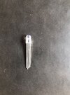
How do I use a voltage regulator as a dimmer or at all?
(It has 3 pins with no indication of input, output)
[I want to be able to change the voltage of Red, Green or Blue to change what general color I get like white, purple, cyan, orange]

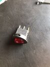
Why does my on/off switch have 3 pins?
(How do I know what each one is for?)

Thank you all for the help & attention!
 

Attachments

  • IMG-20230614-WA0011.jpg
    IMG-20230614-WA0011.jpg
    355.7 KB · Views: 135
  • IMG-20230614-WA0003.jpg
    IMG-20230614-WA0003.jpg
    391.4 KB · Views: 115
Solution
Each LED (Red, Green or Blue) in each module needs its own current limiting resistor.

Different colour LEDs have different voltage drops across them when powered, so the resistors need to be calculated both to suit the supply voltage, the LED type and the required LED current.

As Nigel says, you need higher voltage, such as a boost regulator module running from the battery module.

To control colour brightness individually, you need three separate either voltage regulators or preferably PWM modules.

The 10K potentiometer you show is not a voltage regulator.
Potentiometers can be used a voltage or signal dividers, but only at very small currents - trying to run anything that uses any power (such as a LED) will burn it out.

A boost...
You don't give any details of what anything is (other than the standard little charger/protection board - but it seems fairly likely that the lights need more voltage than 4.2V (maximum) from the Li-Ion cell. A simple voltage converter on the output (another cheap Chinese module) could do that for you.

However, the unknown voltage regulators (with no support components) and random 10K pots make no sense at all.
 
Each LED (Red, Green or Blue) in each module needs its own current limiting resistor.

Different colour LEDs have different voltage drops across them when powered, so the resistors need to be calculated both to suit the supply voltage, the LED type and the required LED current.

As Nigel says, you need higher voltage, such as a boost regulator module running from the battery module.

To control colour brightness individually, you need three separate either voltage regulators or preferably PWM modules.

The 10K potentiometer you show is not a voltage regulator.
Potentiometers can be used a voltage or signal dividers, but only at very small currents - trying to run anything that uses any power (such as a LED) will burn it out.

A boost converter module something like this could be suitable to give you a reasonable working voltage, eg. probably around five to six volts:

Then three of these to control the red, green and blue brightness:


If you don't want to vary the brightness of each colour, then you just need the correct resistor for each LED, running them all straight from the boost converter.
 
Solution
You don't give any details of what anything is (other than the standard little charger/protection board - but it seems fairly likely that the lights need more voltage than 4.2V (maximum) from the Li-Ion cell. A simple voltage converter on the output (another cheap Chinese module) could do that for you.

However, the unknown voltage regulators (with no support components) and random 10K pots make no sense at all.
Yeah, I cant give any details because I literally know the bare minimum of electronics, I would like to know more/where to know more..
 
Each LED (Red, Green or Blue) in each module needs its own current limiting resistor.

Different colour LEDs have different voltage drops across them when powered, so the resistors need to be calculated both to suit the supply voltage, the LED type and the required LED current.

As Nigel says, you need higher voltage, such as a boost regulator module running from the battery module.

To control colour brightness individually, you need three separate either voltage regulators or preferably PWM modules.

The 10K potentiometer you show is not a voltage regulator.
Potentiometers can be used a voltage or signal dividers, but only at very small currents - trying to run anything that uses any power (such as a LED) will burn it out.

A boost converter module something like this could be suitable to give you a reasonable working voltage, eg. probably around five to six volts:

Then three of these to control the red, green and blue brightness:


If you don't want to vary the brightness of each colour, then you just need the correct resistor for each LED, running them all straight from the boost converter.
Thanks, I will check availability of those components here in Mexico.

Then.. If I change the A10k potentiometer for the PWM modules & add a boost regulator module right after the battery to my electronic diagram I drew it would work?

If..the boost converter would allow more Voltage to be sent to the LEDs I would still have to regulate them with resistors, wouldn't that be loss of efficiency?

I would imagine it'd be best that after the boost converter module to add the PWM module and then somehow distribute the voltage equally into different output lines, connecting the LEDs to those.
(Differently from how I drew it)

This way if I manage to distribute the right max voltage to each LED I wouldn't have to use resistors as the PWM module would only reduce their voltage (when max setting is the below the max load of the LED)

Sorry for long explication, still got to learn how to concisely talk about electronics
 
If..the boost converter would allow more Voltage to be sent to the LEDs I would still have to regulate them with resistors, wouldn't that be loss of efficiency?

LEDs (and most types of diode) take no current below a certain voltage, then the current goes up very rapidly with a relatively small increase in voltage.

Without at least a low value resistor for each to balance the currents, the brightnesses are likely to be all over the place and a slightly too low or high setting on the boost converter could mean the difference between no output and things smoking....

If you were using individual two-wire LEDs, those can be arranged in series chains (2, 3, 4, 5) or however many to suit the supply voltage, with just one resistor in each chain so better overall efficiency - but with the four terminal RGB LEDs you show in the sketch, that's not possible, they need a resistor each.


Do you have a type number for the RGB LEDs? There are six terminal types, that can be series connected.

There are also digitally-controlled ones, that run directly on a fixed voltage and the brightness of each colour in each LED module is set by a digital signal daisy-chained through anything from a few up to hundreds!
Thanks for all the help but..

Well.. This would help a lot more if I understood everything, I think I need some PDF or Course to be able to communicate & understand more effectively.

Because of the slight urgency I have on this lighting subject I will find an electrician that may help.me make my whole circuit after that I can just replicate it for my next lamps.

Thanks either way, I will come back here when I have more vocabulary & general knowledge.

If any of you have more resources (PDF, videos, etc) I'll.gladly watch them.
 
You could use an off-the-shelf RGB LED kit?

Things like this are readily available on ebay & amazon etc.


The only other change would be to use a "power bank" module [or power bank] to both charge the battery and provide a 5V output, to run the LED system.

eg. Two wires from the battery to one of these, then everything just plugs together:
 

Latest threads

New Articles From Microcontroller Tips

Back
Top