The light at the end of the tunnel is "right in front of my face".
Ronv,
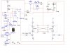
I made a couple adjustments, which I will share with you a little later, but everything is looking awesome. (The timer and NOR Gates are switching sides, I added LEDs to indicate which is on, the ma value from the top to the middle of the H-Bridge are only loosing 0.X ma , and I added a switch to turn the timer off so it can be run without switching so the ma can be adjusted without it switching or event to run constant...)
Anyway, I have a question and/or concern about the Resistor being used in the middle of the H-Bridge.
Obviously the current resistor value of 2.5K is producing the milliamp results that we want, however when this resistor is changed the milliamp value also changes. The design must maintain a Constant Current Value throughout the entire process. So when the Resistance Changes the Current Must be adjusted accordingly. This is why I originally used the LM317 for my Constant Current Source. It should adjust the current based on the Load/Resistance change… At least I think this will occur…
What are your thoughts on this and am I correct that changing the resistor should not affect the current when the current is regulated?
Best Regards,
BHinote
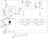
Ronv,
I made a couple adjustments, which I will share with you a little later, but everything is looking awesome. (The timer and NOR Gates are switching sides, I added LEDs to indicate which is on, the ma value from the top to the middle of the H-Bridge are only loosing 0.X ma
, and I added a switch to turn the timer off so it can be run without switching so the ma can be adjusted without it switching or event to run constant...)Anyway, I have a question and/or concern about the Resistor being used in the middle of the H-Bridge.
Obviously the current resistor value of 2.5K is producing the milliamp results that we want, however when this resistor is changed the milliamp value also changes. The design must maintain a Constant Current Value throughout the entire process. So when the Resistance Changes the Current Must be adjusted accordingly. This is why I originally used the LM317 for my Constant Current Source. It should adjust the current based on the Load/Resistance change… At least I think this will occur…
What are your thoughts on this and am I correct that changing the resistor should not affect the current when the current is regulated?
Best Regards,
BHinote
")
 , so all new parts it is...)