Continue to Site

Welcome to our site!

Electro Tech is an online community (with over 170,000 members) who enjoy talking about and building electronic circuits, projects and gadgets. To participate you need to register. Registration is free. Click here to register now.

  • Welcome to our site! Electro Tech is an online community (with over 170,000 members) who enjoy talking about and building electronic circuits, projects and gadgets. To participate you need to register. Registration is free. Click here to register now.

Reversing polarity for electrolysis project

Status
Not open for further replies.

BHinote

New Member
Hello

I am very much a beginner when it comes to electronic circuits, as I only started researching various circuit designs less than 1 month ago. My father has cancer and I am trying to build a circuit for the electrolysis of silver.

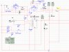
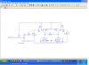
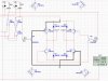
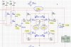
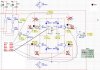
Through trial and error I have managed to build a PWM module for a magnetic stirrer, Developed a Constant Current Circuit that adjusts down to a needed 1ma and a Square Wave timer circuit that will switch on an off 3 times a second up to every 10 minutes.

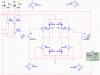
However, I am having trouble creating the “Reverse Polarity Circuit” to tie in with my timer so I can alternate my Positive and Negative wires based on the time adjustment. Since the 1ma is a must I have not been able to find a circuit that simple switches the positive and negative polarity, does not effect the adjusted current and will support as little as 1ma. I have looked at various H-Bridge designs, but they either do not appear to support 1ma or I have not been able to get them to work as designed.

I would greatly appreciate anyone that could please provide any help or at least point me in the right direction. I am running out of time and could use some guidance from someone that actually understands what is or is not possible with electronic circuitry…

Thanks in advance for your time and efforts…

Oh and by the way my Constant Current Source is a 37V Printer Power Supply, that I am adjusting down to between 1ma to 10ma. (More voltage will be required at the beginning of the process to maintain 1ma, but will drop as the process progresses.
 
Last edited:
I do believe your looking for this sort of stuff (Dr. Bob Beck): **broken link removed**

Voltage?

This (LM334) **broken link removed** is an easy to come by current source for up to about 40 V. It only requires 1 resistor to set the current.

Let's get the Open circuit voltage and duty cycle/times nailed first. Battery powered?
 
Last edited:
KeepItSimple...
Thank you for your reply. Your assumption is very close to the project that I am working on, but I am primarily working on a Colloidal Silver Generator. The Lm334 looks like something I could use, if the LM317 that I am using is not the right thing to use.

I am not sure if it will help, but this is the diagram that I have been working on. The second image is the part that is not working and most likely too complex for my needs.

Thank you.
**broken link removed**
 
Last edited:
I hope this works...

The main issue I am trying to solve is how to take the Constant Current Output from U6 (Identified as a LM117, but is actually a LM317) and alternate it between Output A & Output B using the U1 (555 timer) without loosing the adjusted Current value. (i.e. Alternate the U6 output between A & B, based on the timing I have set and not loose the current value that has been set.) I would like to do this without mechanical relays, if possible...

Any thoughts or suggestions would be greatly appreciated, as I have been working on this project for over 3 weeks and this last requirement is kicking my butt....
 

Attachments

  • Colloidal Silver Project A.jpg
    Colloidal Silver Project A.jpg
    287.6 KB · Views: 3,011
  • Colloidal Silver Project B.jpg
    Colloidal Silver Project B.jpg
    298.8 KB · Views: 2,201
Last edited:
Curent Source

You need something to limit the base current thru the transistors, and since the base current represents an error term to your current source you need to keep it as low as possible. I think this will do it. You need high gain transistors like these little guys. There will be 1.01 ma draw from the current sourse with 1 ma to the load so you might want to set the current source 1% high.
Good luck!
 

Attachments

  • cs.PNG
    cs.PNG
    57.6 KB · Views: 866
The base drive on the transistors of the H-bridge is a big error term. Changing to a MOSFET bridge is one idea, OR

Place one of the LM334's in the upper half of the bridge, set for 1 mA each. Q7, pin 2 to output and Q10, pin 2 to output. There the base drive doesn't matter. The LM334 is about the size of a small signal transistor.
 
Ronv,

Thank you for your reply. I will look over your schematic and see what I can make of it. As I do not have any formal training in electronics and have only been researching circuits for a little over three weeks, my understanding of the terminology, what goes were and why is very minimal. I am not quite sure what “Error Term” means, but I assume it is part of what controls the transistors function. I will need to dig into this further to attempt to get a better understanding …

Thanks again for taking the time to reply.
 
Current Source

I marked up the schematic with the problem path. By adding the 390K resistor to the base of the upper transistor only about .01 ma is taken from the current source to turn on the upper transistor instead of almost all of the current.
 

Attachments

  • Colloidal%20Silver%20Project%20B.jpg
    Colloidal%20Silver%20Project%20B.jpg
    262.6 KB · Views: 815
You have possibly 4 options:

You can also put an LM334 in series with the base leads of each of the transistors set to say 0.1 mA or 0.01 mA whatever causes saturation of the bridge transistors. We can figure that out for you.

The idea is Ie=Ib+Ic of the bridge, so the bridge drive, Ib, is added to your setpoint. therefore fixing the base drive to a fixed amount of current makes the error constant. You have two Ib's to deal with.

What your seeing is the ~1mA(Lm317) + Ib (Q7) + Ib(Q8) + Ib(Q10) + Ib(Q9) and these can vary with temperature and other factors. You would rather it be i(lm317)-4*ib and set i(lm317) higher by 4*I(base) where I(base) is controlled.
 
Ronv,
I believe that the attached image has been modified, as you previously indicated. I added R9 & R18 @ 360K and R10, R12, R19 & R21 @ 470K. I placed R7 @ 1K between my two Outputs just to get my Constant Current source to read 12.8ma, as a test. (See the circle at he top of the diagram.) This appears to produce 12.7ma @ my outputs; however I am not sure about the results… The Left Circle is connected to Output-A and indicates +12.8V & -12.7ma. The Right Circle is connected to Output-B and is indicating +56.8mv & 12.7ma. Why wouldn’t the Left side be reading something like +33.4V @ +12.7ma and the Right Side be reading +56.8mv @ -12.7ma? Also after the simulation runs for about 16 seconds it throws an error indicating “timestep too small”… I am not as concerned about the error as I believe it is more of a software issue than a electronic issue…

Again your replies and assistance is greatly appreciated.
BHinote
 

Attachments

  • Colloidal Silver Project B_1.jpg
    Colloidal Silver Project B_1.jpg
    225.1 KB · Views: 1,152
B,
You also need to change the transistors to the ones with higher gain than the ones you have. Since the base current is now very low the higher gain is needed to turn on the upper transistor all (or most) of the way. Right now it looks like it is only partially on. I'll add your current source to my model just to make sure. The current source should drop the voltage to about 10 volts at the top of the H so you get 10ma thru the 1K.
 
Ronv beat me too it.

Try a 2N3904 (npn) 2n3906 (pnp). Good for Vce up to 40 V, Hfe is about 300. Good to 200 mA for collector current.
 
I Source.

Yes I think like KISS says, the transistors need a gain (Hfe) of 200 or so the TIP is only about 40 or 50 I think. It looks ok in the sim. Are you simulating the whole circuit or just this part?
 

Attachments

  • Colloidal%20Silver%20Project%20B.jpg
    Colloidal%20Silver%20Project%20B.jpg
    132.6 KB · Views: 646
KeepItSimpleStupid,
I think I actually understood what you are telling me. If you refer to the attached diagram, would I be correct in my understanding if I did as follows:
1. Remove the resistors that I just assigned to limit the current to each of the Transistors.
2. Connect a LM334 or equivalent to the base input of the four transistors.
If all goes well and my Source Current is 12.8ma, then the output should be about 12.76ma after subtracting 0.01ma for each Transistor in the Bridge…
Although I am only concerned about the Resulting Current, I would hope this is not going to substantially mess with the Voltage as well. (It is my understanding that high Voltage will be required to maintain the Current when the water does not have any silver partials and will require less towards the end when the Parts Per Million have increased…)

Now I need to find something equivalent to the LM334, as the software I am currently using does not have this component. (i.e. Multisim)
Your help is greatly appreciated.
BHinote
 

Attachments

  • Colloidal Silver Project B_2.jpg
    Colloidal Silver Project B_2.jpg
    246.5 KB · Views: 1,263
Use the LM317T in simulation. You might need something with a higher Vce for Q7-Q10 in real life. The 2n3904/2n3906 hopefully is a part that you have.

You have to change the bridge transistors too. These are messing with the voltage right now. Your using an 18 wheeler to transport what can be carried in car.

You need 10 mA and your using what something that regulated 6 Amps? that's a factor of 6000/0.01. Not good.
 
Ronv,

I am simulating the whole circuit. (i.e. Both images from my original post are actually one complete design.)
Again I can not say enough about all the help both you and KeepItSimpleStupid have provided me. I am not 100% sure I have it yet, but I am getting close even if I do not completely understand it. I am sure glad both of you do and are willing to share your knowledge...
Thanks again.
B
 
Latest Circuit Update

Well I made the changes as I understood them, but I am not sure if the results are as would be expected. I am trying to understand the issues regarding Gain and how this affects the result, but I am doing more research to see if I can figure it out.

I guess my concerns now are as follows:
1. The readings in the center of the Bridge indicated only 12.9V rather than something much closer to the 21.8V from the Constant Current Source, at the top right of the diagram. It also appears to show the ma as a negative on the side that is 12.9V…
2. I am not sure that my method of switching the sides is correct, since one of the results is based on the Timer output being OFF. Will the power be provided to each side be based off the voltage applied to the actual IC?

I have 6 NPN mps2222ARLRAG's from BenTronics and 2 NPN NTE123AP's I bought from Fry's. I need to check to see if any of these will work or I will need to buy something different when I get the PNP's (I will actually be near a Fry's Saturday and Sunday, which I hope will have more than RadioShack and BenTronics ever carry...)

I really appreciate all the help I have received and hope that my questions do not frustrate either of you, as I am trying to research as much as I can…

My daughter has a Softball Tournament Saturday and Sunday, so I will not have my laptop with me until later in the day…

Although you may get tired of hearing it, but I again can not thank both of you enough for the time and efforts that you have already provided. Thank you.
BHinote.
 

Attachments

  • Colloidal Silver Project - All.jpg
    Colloidal Silver Project - All.jpg
    95.8 KB · Views: 3,355
1. Q5 still might not be turning on hard enough. You need to put probes such that you can see the E-C drop across that transistor. Current through the load is OK. probably if you reduce the load resistor (100 ohms, 10 ohms, 1 ohm), you'll get out of compliance. Increase the base current. Put a current regulator on the base.

FYI:Here is a IC driver that takes only 100 uA to turn on, but it's unavailable at Mouser. https://www.mouser.com/_/?Keyword=drv8843
 
KeepItSimpleStupid,

Thank you, I will make some adjustments and look into the Driver. I appreciate your help and will post back my results as soon as I get a chance... We are off to a Softball Tournament today and I will not be able to work on this untill late this evening...
Take care,
BHinote
 
Status
Not open for further replies.

New Articles From Microcontroller Tips

Back
Top