Continue to Site

Welcome to our site!

Electro Tech is an online community (with over 170,000 members) who enjoy talking about and building electronic circuits, projects and gadgets. To participate you need to register. Registration is free. Click here to register now.

  • Welcome to our site! Electro Tech is an online community (with over 170,000 members) who enjoy talking about and building electronic circuits, projects and gadgets. To participate you need to register. Registration is free. Click here to register now.

Reversing polarity for electrolysis project

Status
Not open for further replies.
Follow Up

Ronv,
Upon returning to my house, after Softball Practice, I did some more experimenting with your latest circuit.

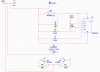
I changed R100 to be 500 ohms, as this appears to be the maximum resistance that effects the 2N3904 setup. Any larger value does not appear to have any effect on the Voltage and/or Amperage output.

My findings are as follows:
The Left Side of the Bridge has a range of 18.5V @ 13.0ma & 9.09ma near R3. (A drop of nearly 4ma.) The minimum values are 3.57V @ 1.78ma & 1.67ma near R3.

The Right Side of the Bridge has a range of 17.4V @ 13.1ma & 8.54ma near R3 (A drop of 4+ma.) The minimum values are 3.45V @ 1.80ma & 1.60ma near R3.

I am still not sure why two sides are different in the simulation and I am also not sure why it does not do down to 1ma near R3.

Things are looking very close, but I have reach a wall with my ability to stay a wake at this time. (To many "up all nights" over the past week or so...) I am going to stop for now and pick it back up in the morning.

Thanks again for all of your time and efforts.

Regards, BHinote


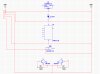
OK, Attached is the modifies simulation. Here is what I did.
I changed C4 to 1 Ufd. I think it may have been 4.7 F. I also took out the pot and replaced it with a 10K resistor. Both just to speed up the simulation. I then let Multisim debug the time steps and other stuff I have no idea about :confused: but it made it happy.:)
You can't read the DC values (in the little yellow boxes) now because it is pulsing, but if you just want to see the values remove U6 pin 6 from ground and wire it to the output of the 7805. Then it won't be switching all the time. Then the yellow boxes give the DC values.
 
Well believe it or not but my original schematic that I started this post with actually had Darlingtons on it. The were floating above and below the H-Bridge and not part of the circuit, because Radio Shack only carried the Transistors that I put in the Circuit... :)

I do not know the pros and cons, as it pertains to the circuit Ronv has designed, so I will defer to either of you for any additional thoughts on this idea...
Regards,
BHinote

Hey guys. Ever thought about replacing the bridge transistors with a darlington?
 
You know, I hate to spoil the party here, since from an electronics point of view this is a very valid and interesting topic.

But it's one that very badly needs a reality check. Which is to say that this entire enterprise is basically junk science, bunkum, folklore and wishful thinking.

I'm not at all insensitive to your situation, and naturally you want to do all you can to help your father. But this is the worst way to do it.

I know something about this, as my own father died of cancer (carcinoma) after a long battle. Having been a total skeptic all his life, towards the end he turned to all kinds of marginal remedies, out of desperation: laetrile (remember that?), acupuncture, other voodoo that was then popular.

None of it helped, and he died a miserable death. Had this happened today, he would have survived a lot longer and been less miserable, because say what you will about corporate mainstream medicine, there have been incredible advances made in the last several decades. (I just had a friend die of glioma, the same brain cancer Ted Kennnedy died of, and he survived a lot longer than Kennedy because of improved treatment--and this was just a couple years afterwards.) I don't like modern medicine any better than you seem to do, but I don't see anything like their results coming from the current crop of witch doctors and New Age opportunists.

Sorry to be so blunt, but if you really want to help him, you won't get sidetracked into such quackery. Someone needs to say this ... I won't say anything more about it here.
 
Last edited:
Rev. 2

Well, learning more about multisim.;)
Here is rev. 2
Changed grounds to digital grounds to make the logic gates happy.
Added Vdd, also to make the logic gates happy.
Changed the 470Ks on the upper transistors to 33k to better turn off top transistors (this was the 3 or 4 ma going down the wrong side of the H.
Changed R10 to 120K to get more current.
Changed R3 to 2.5K so circuit could get both 1 ma and 10 ma without changing R3.
U6-6 and U5-2 are tied to 5 volts so only one side is on. To see the pulses on the scope tie them to digital ground.
 

Attachments

  • Silver -2.zip
    759.6 KB · Views: 199
carbonzit

I am very sorry for your loss and the experiences that you have had to face in your own life.

With that said, it is my decision to pursue this if I so choose. Regardless of what I have or have not found to be the "Truth", "Fairytale", etc... regarding Colloidal Silver, it is my decision to make and will not waste the time of this forum debating a topic outside of electronics.

Last time I checked this is an Electronics forum aimed at helping people with electronic projects, issues, questions and/or concerns and I have an electronic project that I have been working on. So far Ronv and KISS have been gracious enough to help me in this endeavor.

Now for, as you put it, the "Blunt" Part. If you do not have anything constructive to contribute regarding the circuitry, components or even electronics in general, please do not waste our time on this forum debating a non electronic issues. There are plenty of other forums for this type of discussion.

BHnote

You know, I hate to spoil the party here, since from an electronics point of view this is a very valid and interesting topic.

But it's one that very badly needs a reality check. Which is to say that this entire enterprise is basically junk science, bunkum, folklore and wishful thinking.

I'm not at all insensitive to your situation, and naturally you want to do all you can to help your father. But this is the worst way to do it.

I know something about this, as my own father died of cancer (carcinoma) after a long battle. Having been a total skeptic all his life, towards the end he turned to all kinds of marginal remedies, out of desperation: laetrile (remember that?), acupuncture, other voodoo that was then popular.

None of it helped, and he died a miserable death. Had this happened today, he would have survived a lot longer and been less miserable, because say what you will about corporate mainstream medicine, there have been incredible advances made in the last several decades. (I just had a friend die of glioma, the same brain cancer Ted Kennnedy died of, and he survived a lot longer than Kennedy because of improved treatment--and this was just a couple years afterwards.) I don't like modern medicine any better than you seem to do, but I don't see anything like their results coming from the current crop of witch doctors and New Age opportunists.

Sorry to be so blunt, but if you really want to help him, you won't get sidetracked into such quackery. Someone needs to say this ... I won't say anything more about it here.
 
Last edited:
Ronv,

Sorry to ask a dumb question, but is there a difference between "Ground" and "Digital Ground" when it comes to the Bread Board and/or Circuit Board?

I am looking at the circuit right now.

Regards,
BHinote

Well, learning more about multisim.;)
Here is rev. 2
Changed grounds to digital grounds to make the logic gates happy.
Added Vdd, also to make the logic gates happy.
Changed the 470Ks on the upper transistors to 33k to better turn off top transistors (this was the 3 or 4 ma going down the wrong side of the H.
Changed R10 to 120K to get more current.
Changed R3 to 2.5K so circuit could get both 1 ma and 10 ma without changing R3.
U6-6 and U5-2 are tied to 5 volts so only one side is on. To see the pulses on the scope tie them to digital ground.
 
Now for, as you put it, the "Blunt" Part. If you do not have anything constructive to contribute regarding the circuitry, components or even electronics in general, please do not waste our time on this forum debating a non electronic issues. There are plenty of other forums for this type of discussion.

Well, as I said, I won't discuss this further. I do wish you success with your electronics project, which is fulfilling in and of itself. Sorry I can't help here; still learning.
 
I should have covered that a while back. It's a rough topic.

In general you need to keep high current grounds, noisy grounds, reference grounds separated until they are joined together at a single point.

While we are on this subject, bypass capacitors located near the power pins of an IC can keep that IC from oscillating. For the purposes of your circuit 0.1 uf metalized polyester should be fine.

The ground at the bottom of the bridge and the power supply grounds and the ground from the rest of the circuit should meet at one place.

There is a LOT involved in this topic.

I'll bet that with Multisim, it probably expects the power to have some designation such as Vcc and have it connected to a virtual power source.
 
KISS,

I have attached a crude example using grounds. The left being different than the right.

So when you say "separated until they are joined together at a single point" are you saying like the left side and not the right side OR are you saying something else..

BHinote

I should have covered that a while back. It's a rough topic.

In general you need to keep high current grounds, noisy grounds, reference grounds separated until they are joined together at a single point.

While we are on this subject, bypass capacitors located near the power pins of an IC can keep that IC from oscillating. For the purposes of your circuit 0.1 uf metalized polyester should be fine.

The ground at the bottom of the bridge and the power supply grounds and the ground from the rest of the circuit should meet at one place.

There is a LOT involved in this topic.

I'll bet that with Multisim, it probably expects the power to have some designation such as Vcc and have it connected to a virtual power source.
 

Attachments

  • Ground Example.jpg
    Ground Example.jpg
    220.8 KB · Views: 266
Ronv,

This is really looking good now. I am not able to make the timer circuit adjust at this time, but the ma from start to finish looks great...

My daughter needs me to take her somewhere for a while, but I will continue testing it as soon as I get back.

Thanks again for everything you have done.

Regards,

BHinote

Well, learning more about multisim.;)
Here is rev. 2
Changed grounds to digital grounds to make the logic gates happy.
Added Vdd, also to make the logic gates happy.
Changed the 470Ks on the upper transistors to 33k to better turn off top transistors (this was the 3 or 4 ma going down the wrong side of the H.
Changed R10 to 120K to get more current.
Changed R3 to 2.5K so circuit could get both 1 ma and 10 ma without changing R3.
U6-6 and U5-2 are tied to 5 volts so only one side is on. To see the pulses on the scope tie them to digital ground.
 
What you drew is IDEAL, but not practical. Daisy chaining will be fine for all but:

1. Ground of the regulators
2. Ground of the bottom of the H-bridge
3. The daisy chain of all of the other parts.

You can think of 1, 2 and 3 meeting at the power supply ground.

Make sense?
 
BH, The grounds were just a simulation problem in this case, same with the Vdd (no +5 for the 4002).
In real life there a sometimes several "types" of grounds - Power, digital, analog. You like to keep the switching noise from the digital separate from low level analog signals and the same with high power "stuff" like motors or heaters that can create a voltage drop due to high current. You then bring them together at a common point close to the power supply like your picture.
KISS I've been looking at your model, but I don't think it's a Spice model - maybe MIT made their own.
 
Grounds

I understand what KISS is saying as it pertains to the items in the example, which I believe I have reflected in my new example attached.

Where I am not up to speed is recognizing what exactly is considered "Digital".

I am pretty sure I understand the difference between Switches, High power supplys, Motors and Heaters, as Ronv has indicated. However I will probably still mess it up. :D.

Ronv, I am working with it again and will get back to you when I have more to report. It is looking very good now... Thank you for all of your time and effort.

Thank you both for the time you both have contributed...

Best Regards,
BHinote
 

Attachments

  • Ground Example 2.jpg
    Ground Example 2.jpg
    235.8 KB · Views: 240
I gave you all you need to worry about.

1. The bottom of the H bridge
2. The regulator grounds
3. The power supply ground
4. All of the other ones (555, gates, etc.)

These should all be separate paths to a SINGLE point.
 
There is a lot to keep in mind when you are worrying about noise. Maybe more important is power supply decoupling. In the case of your circuit the 555 draws high current when it switches. That is the purpose of the 10 Ufd. cap across it. The cap will supply the power for the short time the current is high. The H bridge has the same problem. When it changes state there is a short time that the 2 transistors on the same side are on at the same time. In this case you can't put a cap there because it would screw up the current source. But the current source tries not to let the current change, but alas, it is not super fast. The best you could do in this case is a cap from the collector of Q8 to the H Bridge ground. Then the battery (power supply) is the common point ground, so a cap here will eliminat probles caused by a long wire to the power supply. The 4001 switches fairly fast so a small capacitor from 5 volts to ground would be good. Last the control input on the 555 has fairly high impedance so is susceptible to noise, thus the small cap there. Often you can find recommendations in the data-sheets.
Having said all this, this circuit would probably work without any of these-just good practice.
 
Sorry

I feel bad when I have to step away, but my Daughter is playing a softball game in about 1 hour and she has to be there in 15 minutes.

I will jump back on as soon as I get back.

Thanks again for all the Time, Effort and Dedication of this project.

Best Regards,
BHinote
 
Your not out of the woods yet. Breadboarding is yet something else to tackle.

I do reccomend that you:

1) Include both current sources
2) Include both output circuits

You might include only one design that drives the LED for the direction of current flow. Although possible, a three terminal Bi-color LED could be used.

Make it relatively easy to "switch them". A couple of "connectors" with jumpers should do it for the most part except a separate connector for the current adjust potentiometer or mount both of the pots and select with a DPDT or 4PDT switch. The output circuit could be done the same way or with a connector.

The 74HCT05 seems to be only available in surface mount. Little boards are available to convert. There could be other options like a ULN2003 (one of my favorite parts).

If you want to make my circuit, the simplest possible, just drive both of the relays with a 2N3904 transistor with a resistor to the base and a resistor to the LED inputs of the OPTOMOS relays. You can keep your LED drivers as they are.

Suggest you make a parts list, possibly in Excel (2003 preferred) and we can suggest what's missing. Resistor wattages haven't been calculated either, but 1/2 W should be OK.

There has always been a rule that in any project the power supply, the real estate (PC board), the case make up most of the cost of a project.
 
Last edited:
Status
Not open for further replies.

Latest threads

New Articles From Microcontroller Tips

Back
Top