Continue to Site

Welcome to our site!

Electro Tech is an online community (with over 170,000 members) who enjoy talking about and building electronic circuits, projects and gadgets. To participate you need to register. Registration is free. Click here to register now.

  • Welcome to our site! Electro Tech is an online community (with over 170,000 members) who enjoy talking about and building electronic circuits, projects and gadgets. To participate you need to register. Registration is free. Click here to register now.

Reversing polarity for electrolysis project

Status
Not open for further replies.
Is this posible?

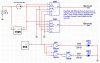
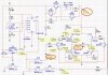
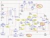
Based on the Schematic Ronv provided, I have been fighting with Multisim and component values all day long and still can not seem to get anything to looks like it is switching the expected current back and forth between the two electrode outputs. I am sure it is just my lack of experience or something, but I am not sure what I should try next or should I just build it and expect it to work?

I want to just believe that it will work, but Multisim was suppose to be my way to prove it works before ordering parts, waiting for a couple days and then finding out that something was wrong…

I only have 9 more days before Multisim’s Evaluation Period will end…

In my mind, the attached mock-up seems like something simple that would work, but obviously it must not be possible or I am sure that it would have been mentioned before.

I initially said I did not want to use Relays, but I should have said “Mechanical Relays”. If they make a DPST IC based Relay that does not affect the Current and/or Voltage being switched and would last, then this seams like it would be a simple way to go.

Again I am just thinking out loud, hopping I get lucky and stumbled on to something…
Regards, BHinote
 

Attachments

  • Simple Idea.JPG
    Simple Idea.JPG
    149.6 KB · Views: 431
Last edited:
Last night I scribbled my version of the design. It's missing a few resistor values. The 74HCT05 is an Open Drain Device, so the R's driving LED's will be ~=(5-1.2)/20e-3 ohms. (5-1.2)10e-3 should work too.

You can even knock off a couple of parts by putting the LEDs in the opto relays in series. The opto relay is an LCC110. (digikey)

The R for the pull up can probably be just about anything from 1K to 10K.

The Lm334 resistor probably needs to be broken into fixed an variable parts or you can use your other current source. The simple LM334 source will be dependent somewhat on ambient temperature.

KISS
 

Attachments

  • E-chem Flip-Flop 001.pdf
    31.6 KB · Views: 312
Last edited:
KISS,
Thank your for providing your drawing. I am looking at it now and will see if I can find Spice models for the parts that are not available in Multisim.

I however have a couple of dumb questions:
1. Resistors for LEDS – I do not totally understand the specs you have provided. [i.e. ~=(5-1.2)/20e-3ohms.] I believe this may be a formula, but I am not exactly sure if it is or not. My guess is as follows:
...a. My guess to the various part of this are
......i. 5 stands for 5Volts.
......ii. 1.2 must be some Ohms Law value or something.
......iii. 20e – not a reasonable clue here.
......iv. 3 ohms – This one is ohms, but I am not sure what it applies to…
...b. So if it is a formula it is saying (5 minus 1.2) div by 20e minus 3 ohms. Or it is a DVR Code to record a TV show sometime next week… :)

2. 74HCT05 -
...a. Multisim has the old 74HC05D_6V, which I know has some internal differences, but do you thing they are similar enough to be substituted in the simulation only or will this not work for the simulation?
...b. Through Hole Package – Unless I am mistaken, I found MM74HCT05N should be correct for Through Hole Sodering or pushing in a socket. Does this sound about right?

3. LEDs & Opto Relays in Series –
...a. I assume Anode between 74HCT05 output and before LCC110 pin #3 input, with Cathode to Ground. (No Resistor required???) This will not pull needed Current away from the 74HCT05 #3 and cause any problems, Right?

4. Analog & Digital Grounds Separate – I am not sure what the laws are here to create separation.
...a. I initially thought this could be accomplished by creating two separate legs extending from ground and connecting Analog to one and Digital to the other, but the still tie back to the same ground. So will this work or do I need to do something else?
...b. Which is Which –
......i. Analog – LEDs, LM317, LM334, 7805, ???
......ii. Digital – 74HCT05, LCC110, Timer, ???

Thank you,
BHinote


Last night I scribbled my version of the design. It's missing a few resistor values. The 74HCT05 is an Open Drain Device, so the R's driving LED's will be ~=(5-1.2)/20e-3 ohms. (5-1.2)10e-3 should work too.

You can even knock off a couple of parts by putting the LEDs in the opto relays in series. The opto relay is an LCC110. (digikey)

The R for the pull up can probably be just about anything from 1K to 10K.

The Lm334 resistor probably needs to be broken into fixed an variable parts or you can use your other current source. The simple LM334 source will be dependent somewhat on ambient temperature.

KISS
 
Are you having trouble with multisim completing the simulation or are the results not what you expect?
I have downloaded multisim, so if you can attach the acutal file I may be able to run it. I may have a learning curve.
Maybe you could post one more picture with the latest at the same time. It runs ok in LTSpice.
Disclaimer. I do have to skip the initial operating point in Spice to get it to run. I think it has something to do with the logic gates interfacing with the rest of the circuit.
 
Last edited:
Unfortunately I am having trouble with both...

Either I do not have enough "ware with all" to understand how to create the right resistance to represent the electrodes so that when the Constant Current is reading ##V @ 10ma or 1ma it will read ##V @ 10ma or 1ma (Slightly less for circuitry) when it reaches the middle of the H-Bridge.

I appreciate all the help both of you have been giving me and I really have not been trying to make either of you do all the work for me, but I am getting very frustrated with myself for not being able to see what it sounds like I should be seeing. (i.e. As of this morning, both of you have taken the time to provide me with circuits that either will or should work, but I can't get the simulator to produce Volts and mAs expected at the middle of the h-Bridge.)

Out of the XX software packages that I tried to quickly learn, understand and had what I though was a good Simulator, I ended up using Multisim. However as with all Evaluations, there are limitations. One of the biggest ones right not is Models for components and the Other is Blowing up on something that should work...

I will not give up, but my personal frustration is flashing "Postal"...

Please find attached a zip file with my recreation of your design "... Ronv_1" and a modified version of the design I started the post with.

Thanks again for you assistance.

Regards, BHinote


Are you having trouble with multisim completing the simulation or are the results not what you expect?
I have downloaded multisim, so if you can attach the acutal file I may be able to run it. I may have a learning curve.
Maybe you could post one more picture with the latest at the same time. It runs ok in LTSpice.
Disclaimer. I do have to skip the initial operating point in Spice to get it to run. I think it has something to do with the logic gates interfacing with the rest of the circuit.
 

Attachments

  • Colloidal Silver Project - Ronv_1.zip
    558.6 KB · Views: 267
I changed the time step to .0001 and made R3 2K so it could get to 10ma and 1 ma. Also shortend the run time to 10 seconds just to make it faster. Seems to work better now (no errors). I have to go now, but will be back later this evening. Let me know if it works ok now. I will also look closer tonight to see if there is anything else we need to do.
 
I am not familiar with the part KISS proposed, but it would sure be simple if it will work.
 
Ronv,
Which Time step? (TMAX...) and where did you change the run time to 10 seconds. I have not found that one yet.
When I run the Simulation and adjust the value of R100, the probe does not change its values. (i.e. V: 34.2V I: 67.1ua)

I appreciate your continued assistance...

BHinote
I changed the time step to .0001 and made R3 2K so it could get to 10ma and 1 ma. Also shortend the run time to 10 seconds just to make it faster. Seems to work better now (no errors). I have to go now, but will be back later this evening. Let me know if it works ok now. I will also look closer tonight to see if there is anything else we need to do.
 
I agree that it does look quite simple, which is always good, but I have been searching the internet for 74HCT05 & LCC110 Spice Models that I may be able to import and have not found anything...

Again I would love to recreate it in Multisim so I can simulate it and then mock Bread Board it (This is one of the things I really like about Multisim. Their Virtual Bread Board. "Helps" to keep me from putting a wire in the wrong hole...)

I am not familiar with the part KISS proposed, but it would sure be simple if it will work.
 
BH,
I'm sorry, I also tied the left 3904 to the output of the 7895 and the right 3904 to ground instead of to the 4001 IC. this lets you see the values. But when I hooked them back up it looked like the 555 was not running, but I am new with the scope.
Look under simulation, interactive simulation settings. Both minimum time step and stop time are there.
 
I am sorry, but Which Left 3904 to were is the 7895 and Which Right 3904 from 4001... Wait a minute, if the Right on is tied to a 4001 of any kind, then the 3904 must be Q5, which would make the left on Q6. So if that is the case, does this mean the Q5 pin 2 is now only connected to ground? (I am not sure how this is going to turn on and off. Also I must be blind, but where is the 7895 or did you mean 7805... Again I am writing this and my brain suddenly says, "Wait" I bet this is simple a test to tune on the Left side and Close off the right... This is not permanent, Right... :)

BH,
I'm sorry, I also tied the left 3904 to the output of the 7895 and the right 3904 to ground instead of to the 4001 IC. this lets you see the values. But when I hooked them back up it looked like the 555 was not running, but I am new with the scope.
Look under simulation, interactive simulation settings. Both minimum time step and stop time are there.
 
Last edited:
Ronv,

I know you were leaving, but I thought I would post this just in case or for when you get back. :)
I have attached to images of the circuit running at around 13mAs. (One with the left side active and the other with the right.)
Anyway my question is why does the left Show 21V/12.9mA @ the Source and 20.8V/10.3mA near R3, while the Right Show 19.3V/13mA @ the Source and 19.2V/9.52mA near R3? (i.e. Lower Voltage and Current in all cases.) I suspect Real Lift situations are not going to be 100% identical, because of tolerances, but is it truly possible that the simulation is faking this difference yet showing the same results for each side... When I see this I start looking for a incorrect value or some type of weird wiring issue...

Just checking...

BHInote
P.S. I have to take my daughter to Softball Practice from 5pm to about 8:30 pm, so if you post something I promise it will be the first thing I see when I get back home. To be honest I have been almost living at my desk, since I started this project... Thank God my daughter has softball or I would only be living at my desk period... LOL

BH,
I'm sorry, I also tied the left 3904 to the output of the 7895 and the right 3904 to ground instead of to the 4001 IC. this lets you see the values. But when I hooked them back up it looked like the 555 was not running, but I am new with the scope.
Look under simulation, interactive simulation settings. Both minimum time step and stop time are there.
 

Attachments

  • Ronv Test - Left Side Active.jpg
    Ronv Test - Left Side Active.jpg
    226 KB · Views: 433
  • Ronv Test - Right Side Active.jpg
    Ronv Test - Right Side Active.jpg
    212.7 KB · Views: 359
Last edited:
KISS,
I agree that your design has K.I.S.S written all over it. ;-) and I would love to plug the Schematic in to see it product the result intended, but I am struggling to find suitable substitutes or Compatible Spice Models for the 74HCT05 and the LCC110. I am sure that what you have provided does what is should, but I am sure you can appreciate the peace of mind that a Simulation would give before ordering part & waiting for their arrival.

In the end, I may have to just go on faith for either design, in hopes of being able to produce what I need for my father's health. His Time is not a guaranty right now and regardless of weather the Colloid will working or not, even it will take time to potentially see any results...

I appreciate all of the contributions that have been made.

BHinote

Last night I scribbled my version of the design. It's missing a few resistor values. The 74HCT05 is an Open Drain Device, so the R's driving LED's will be ~=(5-1.2)/20e-3 ohms. (5-1.2)10e-3 should work too.

You can even knock off a couple of parts by putting the LEDs in the opto relays in series. The opto relay is an LCC110. (digikey)

The R for the pull up can probably be just about anything from 1K to 10K.

The Lm334 resistor probably needs to be broken into fixed an variable parts or you can use your other current source. The simple LM334 source will be dependent somewhat on ambient temperature.

KISS
 
That wierd stuff is just math. 10E-3 is 10 mA or 0.10 Amps.

From the datasheet of the LCC110, Vf is 1.2 and If is 1 mA; we'll use 10 mA. There is virtually no drop across a FET, so it will be neglected.

So, the resistors need to be R=V/I = (5 V - 1.2 V)/0.010 A or 380 ohns, 390 is probably the closest. The other LED drop could be between 1.2 and 2.1 volts.

That lone resistor out of nowhere has have at least 10 uA flowing through it. Lets use 1 mA, so R = 5 V/0.010 = 500 Ohm. use a 470 ohm resistor.

The next resistor to deal with is the current source which might be a bit more difficult.

I'd probably add a fuse/fuseholder if I could find one at the input to the structure, just after the current source. The idea is to protect the opto parts. This one is probably too big. With the current source, I really doubt it's needed though.
 
Last edited:
Rev 2

OK, Attached is the modifies simulation. Here is what I did.
I changed C4 to 1 Ufd. I think it may have been 4.7 F. I also took out the pot and replaced it with a 10K resistor. Both just to speed up the simulation. I then let Multisim debug the time steps and other stuff I have no idea about :confused: but it made it happy.:)
You can't read the DC values (in the little yellow boxes) now because it is pulsing, but if you just want to see the values remove U6 pin 6 from ground and wire it to the output of the 7805. Then it won't be switching all the time. Then the yellow boxes give the DC values.
 

Attachments

  • Silver -1.zip
    186.6 KB · Views: 212
Cool, I will take a look at it and see what I can see. Thanks again for all of your efforts.

As for Multisim, I too am confuse at time with know practical knowledge of electronics and just about three weeks now of fooling around with it. It does however have a really cool Virtual Bread Board. (i.e. Push little Button that looks like it has a bunch of "little " dots on the "Main" tool Bar.)

I hope to give you some type of response before taking my daughter to Softball Practice.

Thanks again.

OK, Attached is the modifies simulation. Here is what I did.
I changed C4 to 1 Ufd. I think it may have been 4.7 F. I also took out the pot and replaced it with a 10K resistor. Both just to speed up the simulation. I then let Multisim debug the time steps and other stuff I have no idea about :confused: but it made it happy.:)
You can't read the DC values (in the little yellow boxes) now because it is pulsing, but if you just want to see the values remove U6 pin 6 from ground and wire it to the output of the 7805. Then it won't be switching all the time. Then the yellow boxes give the DC values.
 
I am still playing with it. Got some numbers @ 12.8ma. Looks like a loss of about 4ma to inside the H-Bridge. Working on the Variable Resister to get down to a range that ends up around 1ma.

Sorry for needing to step away, for my daughter, but you know how that goes. I will work on it more when I get back and let you know what I find.

Regards,
BHinote

OK, Attached is the modifies simulation. Here is what I did.
I changed C4 to 1 Ufd. I think it may have been 4.7 F. I also took out the pot and replaced it with a 10K resistor. Both just to speed up the simulation. I then let Multisim debug the time steps and other stuff I have no idea about :confused: but it made it happy.:)
You can't read the DC values (in the little yellow boxes) now because it is pulsing, but if you just want to see the values remove U6 pin 6 from ground and wire it to the output of the 7805. Then it won't be switching all the time. Then the yellow boxes give the DC values.
 
KISS,

I might be but not one that is compatible with Multisim. It seems to require "Cadence® PSpice®, XS for XSPICE, and MS for Multisim.

BHinote
 
oops, See next post, as I hit the wrong button and did not know this was posted yet...
 
Last edited:
Status
Not open for further replies.

New Articles From Microcontroller Tips

Back
Top