Continue to Site

Welcome to our site!

Electro Tech is an online community (with over 170,000 members) who enjoy talking about and building electronic circuits, projects and gadgets. To participate you need to register. Registration is free. Click here to register now.

  • Welcome to our site! Electro Tech is an online community (with over 170,000 members) who enjoy talking about and building electronic circuits, projects and gadgets. To participate you need to register. Registration is free. Click here to register now.

Reversing polarity for electrolysis project

Status
Not open for further replies.
Understood... I will adjust the Schematic accordingly...
I am moving a couple things around on the Schematic and putting a inventory/parts list together.
After that I am looking up the part to verify if they can be purchased from one place or another... I will be heading down towards Sacramento again this weekend, so I am going to check out Fry's to see if I can pick them up as appose to waiting for them to be shipped. Chances are that something will have to be ordered, so it would then become pointless to pick them up at Fry's...
Thanks again
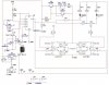
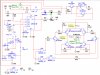
No resistor changes, but we should change the 2N3904 to BC547 and the 2N3906 to BC557. Make sure you look at the picture to get the thru hole part and not surface mount, cause they are really tiny.
 
Your 99% there.

You need a single resistor from the junction of U6d(13) and U6e(5) to +5. Make it 4.7K for now.

The ULN2003
1. Will not have a + power pin
2. COM will be unconnnected
3. GND will be connected
4. Is not sensitive to unconnected inputs

One section of the ULN2003 and 1 resistor COULD be eliminated. The resistors reflect this.

I'll verify the resistor values. Do you have an LED part number/datasheet?
 
If you want to PM me your e-mail I'll try to make you a bill of material for Mouser. They have a nice system you can click on the part and get the data sheet and you can one click the order. I'm pretty sure I can get it done before time to order on Monday, I know you are against a deadline on your simulator.
 
I currently have 3 packages of LEDS. They are as follows:
1. 5mm Red - 2.6Volt, 28mA, 10mcd (Absolute Max Rating 25 Deg. C, Power Dissipation 60mW, Forward current 28mA Max, Peak Wave Length 650nm)
2. 5mm Green - 3.0Volt, 20mA, 40mcd
3. 5mm Yellow - 3.0Volt, 20mA, 55mcd

BHinote
Your 99% there.

You need a single resistor from the junction of U6d(13) and U6e(5) to +5. Make it 4.7K for now.

The ULN2003
1. Will not have a + power pin
2. COM will be unconnnected
3. GND will be connected
4. Is not sensitive to unconnected inputs

One section of the ULN2003 and 1 resistor COULD be eliminated. The resistors reflect this.

I'll verify the resistor values. Do you have an LED part number/datasheet?
 
KISS,

I have added the Resister to the design you were mentioning, see attached, however I am not sure what your statement means. (i.e. One section of the ULN2003 and 1 resistor COULD be eliminated. The resistors reflect this.)

BHinote
Your 99% there.

You need a single resistor from the junction of U6d(13) and U6e(5) to +5. Make it 4.7K for now.

The ULN2003
1. Will not have a + power pin
2. COM will be unconnnected
3. GND will be connected
4. Is not sensitive to unconnected inputs

One section of the ULN2003 and 1 resistor COULD be eliminated. The resistors reflect this.

I'll verify the resistor values. Do you have an LED part number/datasheet?
 

Attachments

  • KISS Bridge 2_B.JPG
    KISS Bridge 2_B.JPG
    105.2 KB · Views: 904
Guys, I don't think you need all the inverters to drive the leds. The 555 can drive them all.
 
Ronv,

This is patterned after your design. How does it look?

BHinote
Guys, I don't think you need all the inverters to drive the leds. The 555 can drive them all.
 

Attachments

  • Ronv Design.jpg
    Ronv Design.jpg
    153.3 KB · Views: 433
  • Colloidal Silver Generator - Final.zip
    283.2 KB · Views: 254
Last edited:
556 Timer

By the way, I am using a 556 timer because I bought one along the way.

Unfortunately I have lots of parts along the way that will probably not be used, but that was before the professionals came on board... :D

If I can not return them and the can not be used, maybe I will have to see what makes them explode... That way I will get more "Bang for my Buck". I know that was bad...

BHinote
 
Required Parts List

Here is my take on the parts needed vs. what I already have.

BHinote
 

Attachments

  • Silver Project - Parts Inventory.pdf
    5.5 KB · Views: 619
  • Silver Project - Parts Inventory.zip
    3.5 KB · Views: 284
I don't think you need D1. When you take it out R16 should be another 220 ohm.
I worry about S2 as the rest of the circuit will still be powered. What was your intent for it?
My comment about the inverters related to the SSR design. I think this will also work and is easier to build, but I can't model it.
 
Ronv,

You guys know better than I do, so I can remove D1. KISS had indicated that LEDs should not really have positive voltage going the wrong way, even though 5V was probably not going to do any harm. So I thought I would add it as extra protection...

MY idea for S2 was to stop the timer so only one side of the H-Bridge would be active and the LED would still be on. Is there a better way to do this?

I can not model specific components of the SSR design either, specifically the LCC110's, but it makes sense so I though I would buy those components too.

BHinote

I don't think you need D1. When you take it out R16 should be another 220 ohm.
I worry about S2 as the rest of the circuit will still be powered. What was your intent for it?
My comment about the inverters related to the SSR design. I think this will also work and is easier to build, but I can't model it.
 
Make R200, R201 closer to 270 ohms, not 390 ohms. ronv's right, the inverters can go if you check the resistor calcs again.

I fell asleep and didn't get to go over thing with a fine tooth comb.

But just a reminder for LED driving (sourcing and sinking).

You have a term Vce(sat) usually from 0.2 to 0.8 volts

You have a supply voltage: 5V or slightly less than 5V (The 555 won't go to 5V, nor 0 volts) It will get close. You would use these numbers if directly driving LEDs from the output of the 555.

You have a LED voltage drop, called Vf. It's 1.2 V for the LCC110. Could be 2.1 or higher for other LEDs.

There is a min/max/typical drive current for LED's. 20 mA typical, 50-70 mA maximum. The LCC110 has a 8 mA typical. Would probably drive at 15-20 mA.

There is Vbr or V(reverse breakdown) for the LED and all diodes. The mechanism is usually non-destructive. Depends on design.

There is resistor power rating: (I^2)*R; 1/2 W should suffice

LEDs age, output does diminish over time. There is lots of variation.

Basic formula is (5-Vce-Vf)/I for that series resistor.

I had intended in one of the designs to place the LED's in the optocouplers in series, hence R was higher.

These guys: https://www.electro-tech-online.com/custompdfs/2011/06/156946.pdf Bi-color 3-lead LED's are avialable in common anode/common cathode versions. Not a real common part, but usefull. They glow yellowish when the polarity alternates fast enough. That particualar part is from www.jameco.com This is when panel space, cool factor come into play. I designed a peak detector, pulse extender and I used one. 50 Hz signal. If it exceeded +-10V, the approprite color showed up for 1 second, so you can see it.
 
KISS,

You are right... I should be using the graphs and I should have a better understanding of everything you indicated about sourcing and sinking, terms, Vce(sat), Vf, Vbr, (5-Vce-Vf)/I, etc... However this truly is my problem, I do not understand a lot of these things and some of the things I thought I understood have turned out to be wrong as well.

I hate to have come so far only to be so confused right at the end that I am not sure if I should order parts or not...

I have tried not to through my hands in the air and wait for someone else to do it all for me, but it is those things that you mention that I defiantly do not have a grasp on at this moment. I am trying to follow along, but I am not sure there is enough time for me to comprehend all that is at play... I can perform the calculations from the formulas that you may provide, but I do not currently have the ware with all to understand what and where these values come from...

As always, your help has been greatly appreciated.

BHinote

555 DATASHEET: https://www.electro-tech-online.com/custompdfs/2011/06/LM555-1.pdf

Note that at a 10 mA load, there is a 1 V drop in the high output. You need to use the graphs.
 
I think for the most part your set. I'll continue to look at it. Migraine, recovery and catch-up takes a while. The main trigger is weather changes. Crief comments are:
These are mostly questions.

1. Need a small cap on the output side of the 5V regulator (0.1 uf) should be fine.
2. I'm still confused about the manual mode of plating polarity (S1)
3. Reverse polarity protection? A fuse/ and reverse biased diode across the 37 V input is one such way.
4. Misc parts. (assuming breadboard)
5. Connectors to bring switches, pots outside of the board?
6. Breadboard choice, if your going that route?
7. In the SSR version, rather not try to eliminate the inverter/drivers.

Fig 8, here https://www.electro-tech-online.com/custompdfs/2011/06/P2514.pdf is what I used for resistors for a 0.042 hole.

I've been happy using pattern I https://www.electro-tech-online.com/custompdfs/2011/06/P2514.pdf . See the next page.
 
Plating mode select switch suggestion

I may have a better way to force the direction. Threshold and trigger are tied together, so locate this point, call it C.

Take an SPDT ON-OFF-ON switch and tie the center terminal to C. Tie an outer terminal to Vcc and tie the other outer terminal to ground.

So, the switch would be labeled, FWD, Normal, and REV.
 
You guys know better than I do, so I can remove D1. KISS had indicated that LEDs should not really have positive voltage going the wrong way, even though 5V was probably not going to do any harm. So I thought I would add it as extra protection...

The LEDs should not be reverse biased more than 5 volts, but since there is 5 volts on the other side of the LED it is not reverse biased at all.

MY idea for S2 was to stop the timer so only one side of the H-Bridge would be active and the LED would still be on. Is there a better way to do this?

If you remove the reset pin from +5 and add a resistor (10K) from reset to +5 instead, you could then use the switch to ground the reset pin and stop the timer.
 
Yes this will work beter.

Thanks again for you help.

BHinote
I may have a better way to force the direction. Threshold and trigger are tied together, so locate this point, call it C.

Take an SPDT ON-OFF-ON switch and tie the center terminal to C. Tie an outer terminal to Vcc and tie the other outer terminal to ground.

So, the switch would be labeled, FWD, Normal, and REV.
 
Status
Not open for further replies.

Latest threads

New Articles From Microcontroller Tips

Back
Top