Continue to Site

Welcome to our site!

Electro Tech is an online community (with over 170,000 members) who enjoy talking about and building electronic circuits, projects and gadgets. To participate you need to register. Registration is free. Click here to register now.

  • Welcome to our site! Electro Tech is an online community (with over 170,000 members) who enjoy talking about and building electronic circuits, projects and gadgets. To participate you need to register. Registration is free. Click here to register now.

Reversing polarity for electrolysis project

Status
Not open for further replies.
I will test this as a option as well.

The SPDT Center Off idea appears to be working, as well, pluse it provides the ability to set to Left, Alternate or Right.

Thank you,

BHinote
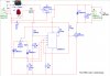
The LEDs should not be reverse biased more than 5 volts, but since there is 5 volts on the other side of the LED it is not reverse biased at all.


If you remove the reset pin from +5 and add a resistor (10K) from reset to +5 instead, you could then use the switch to ground the reset pin and stop the timer.
 
I will check back

Heading to a Softball Tournament.

I will check back before heading for home.

Best Regards,

BHinote
 
Waiting for Parts / PWM Verification

I am still waiting for parts and my simulator expires in 2 days.

So I thought I would post my PWM design, just in case someone noticed a blaring issue I did not consider. (It is currently functioning on a bread board, but that does not allways mean that it is correct.)

Anyway, I again want to thank both KeepITSimpleStupid and Ronv for all their time, efforts and commitment to making my circuit the best it could be...

Best Regards,

BHinote
 

Attachments

  • Fan PWM Control - Best Design.jpg
    Fan PWM Control - Best Design.jpg
    118.7 KB · Views: 304
Last edited:
I would tie the reset pin directly to pin 8 and remove the 220 Ufd. across the motor. If you are worried about motor noise add a .01 Ufd. across the motor at the motor terminals. R7 is not needed as the 555 drives both high and low. How much current does the motor take?
 
Last edited:
Ronv,
Thanks for the quick reply...

I tested a couple of your sugestions and received the following results:
1. Change C4 from 220uF to .01uF. Result: 220uf=(240hz - 270hz) ; .01uF=(116hz - 260hz)
2. Connect Rese to pin 8 and remove R7. (Timer never started. Please see my thoughts below)

Thoughts: Based on my understanding, I designed about a 2 Second delay in the timer so that it would initially start with close to 12V and then adjust once the time started junctioning. With that all said, when I changed Reset to pin 8 and/or removed R7 from the circuit I beleive R3 and C5 do not allow pin 4 & 8 to build enought voltage.

What are your thoughts?

Best Regards,

BHinote

I would tie the reset pin directly to pin 8 and remove the 220 Ufd. across the motor. If you are worried about motor noise add a .01 Ufd. across the motor at the motor terminals. R7 is not needed as the 555 drives both high and low. How much current does the motor take?
 
Cost Reduction

:DI guess a picture is worth a thousand words.:) Pin 8 and 4 would still go to +12. R3 could go away. The reset is a neat idea, but the turn off is much less graceful than the turn on. But it certainly doesn't hurt anything.
 
Ronv,

I did not see one part of your reply, about the current of the motor.
I believe that it takes 0.12A.

After reviewing my delay circuit, I discovered that it was not actually providing 12V non-pulsed. It appears that the timer was not doing anything.

I believe that i need to build something to hold pin 2 (Trigger) to ground for about 2 seconds to cause the output to go high for 2 seconds. (i.e. Start the motor with full power and then drop back to whatever the Potentiometer was lasts set at.

Best Regards,

BHinote

I would tie the reset pin directly to pin 8 and remove the 220 Ufd. across the motor. If you are worried about motor noise add a .01 Ufd. across the motor at the motor terminals. R7 is not needed as the 555 drives both high and low. How much current does the motor take?
 
You know you are Right...

Ronv,

If I am slightly qualified enough to say this, "I agree". ;)

I just posted something similar when this one came through...

I have removed R3 & C5 and I connected Pin 4 to Pin 8. (This all works well...)

So now my only issue is how to make the timer output High for 2 seconds and them go into the regular pulse.

I am experimenting with a NTE123ap or 2n2222 transistor and the R3 / C5 idea, but this is not working at this time. (Back to searching the internet...)

Best Regards,

BHinote


:DI guess a picture is worth a thousand words.:) Pin 8 and 4 would still go to +12. R3 could go away. The reset is a neat idea, but the turn off is much less graceful than the turn on. But it certainly doesn't hurt anything.
 
Concur with 220 uf being way to big. A 0.1 uF ceramic cap for brush noise suppression. The frequency you'll have to play with. The beauty of PWM means the torque is constant. but the motor has to be able to respond. 0.001 Hz is too slow and 1 MHz is too fast. Motor may "sing" at audio frequencies.

MATH: Never use .1. ALWAYS use 0.1. i.e. Always use the 0. when the decimal is less than 1.
 
KISS,

0.1 Check...

Thanks :)

Concur with 220 uf being way to big. A 0.1 uF ceramic cap for brush noise suppression. The frequency you'll have to play with. The beauty of PWM means the torque is constant. but the motor has to be able to respond. 0.001 Hz is too slow and 1 MHz is too fast. Motor may "sing" at audio frequencies.

MATH: Never use .1. ALWAYS use 0.1. i.e. Always use the 0. when the decimal is less than 1.
 
Nudge Please

Ok, so I have been searching the internet for a good way to force the Timer Output High for 2 seconds before resuming normal operation and have not found anything yet.

I believe I need to force Trigger to ground and then resume normal function, but I am not having luck with NPN or PNP transistors.

Could someone Nudge me in the right direction?

Thank you,

BHinote
 
Reset

The 555 is reset with a low on the output - you need a high to turn on the FET. So we could invert the output with a circuit like this. We could also change to a PFET, but good one can be hard to find.
 

Attachments

  • Inverter.PNG
    Inverter.PNG
    53.7 KB · Views: 239
Reset

You might want to add a diode (the 4001 is ok) to "reset" the reset circuit. Otherwise it will take a long time for it to get into reset mode again after power has been on. Also note the reset line switches at 0.4 volts:p so you only have about 0.5 seconds:rolleyes: with full power. If the little motor doesn't start in 1/2 second it probably won't run there anyway. One of the nice things about PWM is that you get pretty much full torque throughout the speed range.
 

Attachments

  • reset.PNG
    reset.PNG
    69.5 KB · Views: 224
Ronv,

I had to leave for my daughters local softball game and just receive your post.

Thank you for replying back so quickly... I am going to do some tests with what you provided.

As always, your help is greatly appreciated.

Best Regards,
BHinote
You might want to add a diode (the 4001 is ok) to "reset" the reset circuit. Otherwise it will take a long time for it to get into reset mode again after power has been on. Also note the reset line switches at 0.4 volts:p so you only have about 0.5 seconds:rolleyes: with full power. If the little motor doesn't start in 1/2 second it probably won't run there anyway. One of the nice things about PWM is that you get pretty much full torque throughout the speed range.
 
Ronv,

On the Simulator, everything worked well, however on my Bread Board the circuit worked a little different. I was able to achieve my desired time period, but the motor did not turn on for that period of time rather than running at 100% before returning to the adjusted Pulse Width.

I have experimented with this for a while and eventually migrated to a 556 timer. Now I am using the first timer to provide +12V for 2 seconds and then go to 0V. Based on the Simulator I took the output of Timer A and attached it to the Trigger of Timer B, witch appeared to do as I expected. However I soon discovered that on the Bread Board it did not work either.

What I have determined is that when I set the Trigger of Timer B to Negative, after it has first been initialized with power, it will cause Timer B to run the motor at Full capacity.

This is what I want, but I need Timer A to establish a negative connection and then open the circuit so the normal operation will continue. (i.e. A Normally Open, Electronically controlled, SPST, Digital Switch.)

Through Trial and ERROR, if have now made my 556 timer stop working on the motor side, although I am not sure why…

Is there an easy/cheap way to open and close a connection electronically?

Best Regards,

BHinote
P.S. I found that the software I have been using does not have sophisticated Trial Periods. I backdated my machine to a week ago and found that I now have 7 more days to evaluate it. :D . I am not sure if this will continue once I let the trial period laps, but is does give me a few more days to finish things up…

You might want to add a diode (the 4001 is ok) to "reset" the reset circuit. Otherwise it will take a long time for it to get into reset mode again after power has been on. Also note the reset line switches at 0.4 volts:p so you only have about 0.5 seconds:rolleyes: with full power. If the little motor doesn't start in 1/2 second it probably won't run there anyway. One of the nice things about PWM is that you get pretty much full torque throughout the speed range.
 
Wait a minute…

I believe I need a Relay rather than a switch…
I will look for one that will work…

BHinote
Ronv,

On the Simulator, everything worked well, however on my Bread Board the circuit worked a little different. I was able to achieve my desired time period, but the motor did not turn on for that period of time rather than running at 100% before returning to the adjusted Pulse Width.

I have experimented with this for a while and eventually migrated to a 556 timer. Now I am using the first timer to provide +12V for 2 seconds and then go to 0V. Based on the Simulator I took the output of Timer A and attached it to the Trigger of Timer B, witch appeared to do as I expected. However I soon discovered that on the Bread Board it did not work either.

What I have determined is that when I set the Trigger of Timer B to Negative, after it has first been initialized with power, it will cause Timer B to run the motor at Full capacity.

This is what I want, but I need Timer A to establish a negative connection and then open the circuit so the normal operation will continue. (i.e. A Normally Open, Electronically controlled, SPST, Digital Switch.)

Through Trial and ERROR, if have now made my 556 timer stop working on the motor side, although I am not sure why…

Is there an easy/cheap way to open and close a connection electronically?

Best Regards,

BHinote
P.S. I found that the software I have been using does not have sophisticated Trial Periods. I backdated my machine to a week ago and found that I now have 7 more days to evaluate it. :D . I am not sure if this will continue once I let the trial period laps, but is does give me a few more days to finish things up…
 
The 555 is reset with a low on the output - you need a high to turn on the FET. So we could invert the output with a circuit like this. We could also change to a PFET, but good one can be hard to find.

Did you add the inverter transistor?
 
Yes, but for some reason the motor just did not start for 2 seconds and then it turned on at normal speed.

When I tested it in the Simulator all appeared to work as expected, however so did my original delay Resistor and Capacitor idea... When I put it to the bread/project board is when it does not work as expected. Another thing is that when I applied the "inverter Transistor" it changed the direction of the potentiometer. (i.e. Originally Turn Left for slower and Right for Faster; Now Left for Faster and Right for Slower.) This really does not matter, but I thought I would point it out.

I found a 4n25 Optocoupler / Phototransistor with Base connection on a old alarm circuit board I have. I am checking to see if I can use this to connect Trigger to Ground and then open the circuit. Do you see any reason why this will or won’t work?

Best Regards,

BHinote

Did you add the inverter transistor?
 
Interesting. That circuit doesn't like to start. Do you need the pulse to the motor? Will it not start on the lower speed settings? If so I'll look some more tomorrow.
 
Status
Not open for further replies.

Latest threads

New Articles From Microcontroller Tips

Back
Top