Continue to Site

Welcome to our site!

Electro Tech is an online community (with over 170,000 members) who enjoy talking about and building electronic circuits, projects and gadgets. To participate you need to register. Registration is free. Click here to register now.

  • Welcome to our site! Electro Tech is an online community (with over 170,000 members) who enjoy talking about and building electronic circuits, projects and gadgets. To participate you need to register. Registration is free. Click here to register now.

Reversing polarity for electrolysis project

Status
Not open for further replies.
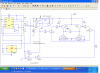
Not sure if you built it or are simulating it. Anyway if you check the spec. on the 2N3906 it has a gain (hfe) of 100 minimum at Vce of 1 volt. So in your case the base current is 58 ua so you can only be certain that you can get 100 times that much or 5.8 ma from collector to emitter with a drop of 1 volt. Since we are asking for 10 ma the voltage from collector to emitter has gone up. The easiest way to fix it if you have built the circuit is to change the 360k resistors to 150k resistors to increase the base current. If it is only the simulation use the transistors in my sim or some other with higher gain (200). https://www.electro-tech-online.com/custompdfs/2011/06/2N3906.pdf
In playing around with it there will be another problem. The LM117 will maintain regulation down to 10 ma minimum (3.5 typical). Normally this isn't a big deal. We can just add some load before the current sense to increase the current. The trouble is that to get the 5 ma at 2 volts or so take 400 ohms. That turns into 92 ma at 37 volts, so the resistor gets pretty big (5 watts).
 
I should have clarified this before now, but I am actually using a LM317 and not a LM117. Multisim 11 does not have a LM317 model, so I used the LM117 just to try to simulate my needs. Sorry for not identifying this on the drawing or making sure both of you understood this before now... I hope this did not waist your time...

Anyway, except for buying a lot of parts that I am finding are not right for my needs I have been trying to create a working simulation before I fry parts or put something together that simply does not work...

I have prototyped the Constant Current Circuit with the LM317 to confirm that I could create the adjustable constant current from 10ma down to around 1ma, which I was successful in creating. However the timer circuit and Alternating Current Circuits have only been prototyped in hopes of seeing it work before assembly... Unfortunately, each time I thought I found a circuit, on the internet, that I though would work I bought the parts hopping that I could assemble it there after... No such luck, just wasted good money proving i did not know what I was doing.

To be honest I am willing to scrap all of my simulations and parts, if they will not actually do what I need. I have know practical knowledge of Electronic Circuitry and everything I have designed to this point has been created with 3 weeks of internet searching and research, including downloading 10 different simulate products trying to find one I could use to hopefully see it work before building something that never would... I am trying to be as self-sufficient as possible so as not to expect someone to do all the work for me, but honestly I have not learned enough in three weeks to finish the job on my own which is why I posted on this forum. Anyway I am not going to give up as this is too important for my dad's potential health, but clearly I do need expert help like both of you have been providing to actually build something that will work...

I initially looked at the L293D and the SN754410NE drivers used for robot motors, but I was afraid that they would not support current down to 1ma and could only be ordered from the internet...

Anyway I am currently staying in a city that has a Fry's Electronics store, so maybe with the help both of your have been providing I will be able to buy some more parts before I leave... :)

Thanks again for both of your interest and continued support of my needs...
 
Project Recap
My Voltage/Current Supply is sourced from a HP Printer power supply that provides 37V and up to 400ma.
I am trying to build a Circuit that will provide Constant Current adjustable from 10ma down to about 1ma and has the ability to swap/flip flop polarity from several times a minute up to around every 10 minutes.
This circuit will be used in the electrolysis of Silver in Distilled Water. (i.e. Colloidal Silver) The Distilled Water is the reason for the 37V power supply, as high voltage will be required to sustain constant current during the initial phase of the process. (i.e. No real resistance in distilled water.) However as the process works on the silver, the resistance will increase, which should make the constant current regulator drop the voltage as the resistance is greater. The polarity swapping is designed to keep the anode from building up during the process... Anyway I hope this helps to paint the big picture and give a better understanding of what I am trying to accomplish.
BHinote
 
Do either of you think is could save a lot of head aces if I us something like a NTE1749, NTE7196, L293 ??? or a SN754410? Although I was trying not to go with a component that I had to order, it looks like I may have to order parts before I am all said and done anyway. My main concerns with these type of components is weather they will support down to 1 ma and not mess with my Constant Current Source's adjusted output...
I am still willing to pursue the Transistor method, but if this would simplify the requirements and save any headaches I am causing either of you, then...
BHinote
 
Your using a part for a non-standard application, so you have to buy and try. In reality, you need a few power supplies and the ability to set the logic levels and the ability to check whether 1 mA is good enough. Application engineers can also help. Selecting a low current output driver increases success. Selecting a MOSFET bridge increases success even further. Parts availability is yet another.

Except for the bridge, the design is relatively straightforward.

To support the low current (1 mA) a MOSFET bridge would be more suitable. Why? Just because the MOSFET is a voltage controlled device rather than a current controlled device.

Now to throw a big wrench in the fan with a totally off the wall idea is to use an optocoupler as the output device. https://www.electro-tech-online.com/custompdfs/2011/06/4N26.pdf

or a FET version https://www.electro-tech-online.com/custompdfs/2011/06/H12FH11F1M.pdf

Higher current FET relays are available as well.

This kills the the compensation for the error terms that are giving the most headaches because the transistor or MOSFET is controlled with light. Drive is now cake.

If I were you, I'd build this in two pieces. the driver and the timer.

I hope you tried manually, the constant current source.

Being totally wierd, you could use two power supplies and two relays (optomos or conventional) and 3 electrodes. (3 electrodes, so deadtime isn't an issue)
Optomos relays: http://www.clare.com/home/pdfs.nsf/www/CPC1788.pdf/$file/CPC1788.pdf

I like to put all the ideas on the table and then kill them one by one.

As I see it, you want to build one and you want to build it quickly and reliability isn't that important and neither is size. Dead time or the amount of time before polarity switches may be a problem. e.g. ON(fwd), OFF(100 uS), ON(REV) may be even more reliable. With 3 electrodes, it doesn't matter. With such low currents, it probably doesn't matter.

Leakage currents, from the devices that are OFF havn't been addressed.

My vote:
Four FET Optocouplers or OPTOMOS relays. The latter is more expensive.
 
Last edited:
"Holy cow batman!!!" ;-) That all looks very interesting and scares the crap out of me at the same time, as I really do not have any real knowledge to go on here.

I recognize you are the expert and respect your opinions, in these matters…

You are correct in saying that I need to build one as quick and reliable as possible, within realistic terms of time required to accommodate both. You are also correct in saying that size is not a factor, as it pertains to being micro or not. However being larger than the size of a hard case for Reading Glasses might start to become less appealing yet I somehow do not believe this would be an issue…

The three electrode idea sounds interesting, but I am not sure how this would all work out since the electrolysis occurs between a cathode and anode parallel to each other. If we went in this direction it would most likely have to incorporate 4 electrodes. This means 4 times the cost of the .9999 silver and would really get expensive fast…

Although I almost always try to put too many bells and whistles on my projects (i.e. Overkill), I still like to keep what’s under the hood as simple and clean as possible. (i.e. K.I.S.S.) What I mean by this is as follows:
1. All of my research has lead me to believe that 1 to 1.5 ma of constant current will produce the best result, but I have seen cases that have used 10ma as well. The one thing I do know is that I must prevent “Current Runaway” as the conductivity increases throughout the process. This is why I am trying to us a Constant Current Regulator, which is the only piece of this puzzle that I have put on the bread board… (I did bread board the PWM circuit, but that is not relevant to this topic.)
2. Because the electrolysis of the silver eats away at the anode and corrodes the cathode, I have found research that indicates alternating these electrodes will wear both evenly and minimize corroding. However I have not determined what the best timing for this is which is why I have the timer able to adjust this. Again out of my field of expertise, but I believe that the time between switching will not be critical, as the conductivity/resistance of the water remains the same each time the process is shut off, witch means that when turned back on the resistance should still be about the same as it was when shut off.

I agree, Leakage could be an issue as I was hoping OFF=0V and ON= ?ma as set by the Constant Current Source.

In all likelihood, the voltage required to sustain the 1-10ma will never require the full 37V and 400ma available with the Power Supply, so I assumed that it would be able to supply voltage for management as well as provide the Constant Current. However you obviously know more about this than I do…

If FET Optocouplers would be best then who am I to say otherwise? As far as I can tell, Multisim does not include Optocouplers, so I may not be able to simulate the design before trying to put it on the Prototype Board…

As for cost, $8 or $10 dollars more is not a deal breaker, but substantial expense might need to be considered. The end result is I need it to do the job for the potential of my dad’s health…
Regards,
BHinote
 
KeepItSimple...,
I am sorry to ask this, but to you know where I might find any examples of circuits using this technology? With know practical knowledge, I have to start with something and then deconstruct to reconstruct what is needed which I am sure you could tell by the components that I started this post with... Also if any of what I will need might be at Fry's Electronics I am still in the city that has one. I highly doubt that my local radio shack will carry any of what may be needed and Fry's is 2.5 hours from where I live...
 
We can do it with Fry's parts. Let me model the whole thing so you can be sure. You have done a great job getting to where you are!
 
Off to softball tournament finals... My daughter's team was the number one seed yesterday, so late games today. I will try to check back later, before leaving for home.
Have a great day...
 
Thanks Ronv. I am trying hard to be as self-sufficient as I can , so as not to abuse either one of you, but I am honestly floundering at the moment as I am sure both of you can tell. I have been trying to figure the Polarity Revering circuit out for well over a week, before ever posting on this forum. (i.e. Not just expecting someone to do it for me as I have seen many posters expect...)

Thanks again for all the time you both have given me. It is "greatly appreciated".
Regards,
BHinote
 
The multiple electrode idea gets thrown out for various reasons, but it was on the table.

400 mA is an issue. So is 10 mA when you combine them with a 1 mA requirement. A 400mA and a 1mA may mean a Lm317 type current source and a LM334 type current source. I wasn't aware of the 400 mA issue until recently. Ahh!, you did say 400 mA available. The 400 mA power supply doesn't mean much, if you need only 10 mA delivered to the electrode, but it does mean something because you'll need about 20 mA to drive each LED.

The 400 mA issue may force an Optomos part.

The 1 mA issue means that a single standard DPDT relay (an option not considered) may not be viable because of wetting current requirements.

Your already found out the error issues at low currents.
 
Last edited:
KeepItSimple...,

I am positive you are correct, as I do not have the expertise in this field. Based on the research regarding Colloidal Silver, I found my systems that were using 200ma, 300ma as well as 400ma Power Sources. I guess I figured that based on my tests with the LM317 (Large Heat Sink) that it would only pull what it required. (i.e. Potentiometer adjusted between 1oma and 1ma...) I then assumed with a 7805 pulling a second line with 5V the Power Supply could be Christmas Treed (i.e. Split Off) in to various other slices and the 37V, 400ma Power supply would deliver what was needed... I don't know... I guess what seams logical defies the electronic laws...

Although wishful thinking, I though the Multisim software was suppose to do the confirming for me... (i.e. Protect be from my own ignorance... Blow up in software, before blowing up in my face... LOL I guess if I do not tell the Simulator that I have a power supply with 400ma it could not tell me anything anyway...)

Being honest, I am in very uncharted territory now as I have not actually reviewed any examples, in my prior internet research, that addressed these issues or used the technological direction you have suggested recently. As I said before, both of you would be considerd geniuses compared to my practical knolege, so I am sure you are right. However this does mean that my current ability to take a suggestion and "Walk With It" ;-) has dropped to a crawl. You might even say that I would look closer to flat on the floor right now. LOL

Anyway, I apologize for being so infantile in my understanding of these things. I am logical, mechanical and usually can take things apart look at them reconstruct what I need from what I see, but this challenge is getting the best of me.

For Me Giving up is not an option & by the way both You and Ronv have continued to help and assistance me to date, I can tell neither of you give up easily either. I do realize that both of you have lives too, so reasonable time and assistance has it's limits. I do appreciate everything that has been provided, even if it proved to show how flawed my ideas actually were... LOL
Thanks again... Back to the Tournament...
Regards BHinote
 
Last edited:
The resistivity of water is about p (Rho)=18 M ohm-cm. Resistance is pL/A. My chemistry background is horrible.

But, I think we can guess at the initial power requirements based on the resistivity and the distance between the electrodes (L) and the area of the electrodes.

Area might be hard to estimate, but if this were a wire, I'd probably assume it all. If it were a plate, i'd assume probably one side and possibly a small fraction of the other side.

So electrode area, spacing and water purity will determine the voltage/current to start the reaction.

-----

The optocouplers are easy to employ. They interface as LED's on the control side. LED's have a Vf parameter and an If parameter. Simple LEDS If is about 20 mA and Vf is about 2.1 V.

You can place two LED's in series with one resistor or LED's in parallel with a resistor for each LED.

Examples (LED's switched on with a transistor having Vce(sat) of 0.6V

5V supply (1 LED)
R ~= (5-0.6-Vf)/If

12 V supply (2 LEDs)
R ~= (12-0.6-2*Vf)/If
 
tournament is over, time to head for home.

I stopped by a starbucks to check before I hit the road...

I am using Steam Distilled Water (0 parts per million). It will be heated to around 115 deg. or so. (Just below Boiling) to increase the initial conductivity of the water.

As for the the silver service area, I am not positive right now, but both Cathode and Anode are 1 troy ounce each. Based on a web site I found approximately 28mm x 50mm (1 1/8inches x 2 inches)

They will be about 1 inch apart. (parallel)

It will take me about 2.5 hours before I get home, so I hope I have answered your questions.

Best Regards,

BHinote
 
The 1 mA is probably pretty reasonable as an initial current, but you may have to have them spaced a little closer to get the reaction to start. If you have the silver, you could try starting the reaction with just a power supply. You should be able to mechanically clean the electrodes. Don't use the result.
I sincerely doubt that you will even use the 1 mA setpoint. You'll just pick a value of current and go with it. Once the current reaches a particular value, you'll probably stop the reaction. This is just an educated guess at this point.

Assuming a consistant electrode spacing, you should be able to use a particular DC voltage across these points to stop the reaction. Current would be better. A DC voltage would be easier to implement.

These are just thoughts.

I did electrolysis of water at home when I was a kid and generated Hydrogen and oxygen. I did have access to a small amount of a platinum screen and used DC.

We had a deionized water system at work. It's not the same as distilled. For one part of the process there was a secondary filter system used as the water always ran in a continuous loop. That system was entirely filter based (2 banks) with a UV source that killed bacteria.
 
Current Source

OK. I could not get the LM317 to act right for all the conditions, so here is the Fry's special.
Sorry, it is a bit more complicated but I think it will work for you.
Here are some things I noticed along the way.
The 10Ufd on the Con pin of the 555 should be a .01ufd.
You should have a 10 ufd. from 5 volts to ground at the 555.
I simulated with 4.7 Ufd. for the timing cap on the 555 and get 3 seconds or so with the pot at 50%. That would make your timing 300 seconds at 50%. I'm guessing this is what you want.
I didn't know what S2 Motor was so I tied the input of the NOR blocks to ground to make them active. Is S2 a timer or something?
I would make R8 220 ohms for the LED.
So here are the changes:
Replace the 317 with a current source.
Replace the base resistors with 150K,
Replace the transistors with Fry's available.
With this setup the single pot should get you from 1ma to about 12 or so.
I'm not sure I understand how this works since it would appear that it just plates from one electrode to the other and then back again. Does some of the silver stay in solution?
If so it won't take long for the resistance of the water to go down.
 

Attachments

  • CS2.PNG
    CS2.PNG
    89.1 KB · Views: 411
  • CS2.1.PNG
    CS2.1.PNG
    69.5 KB · Views: 454
The whole point is to get the silver into the solution and to have as pure of a silver/water mix as possible.

Just as you would use an AC voltage for water detection, you use AC here. The crud builds up on one electrode and you have to remove it by reversing the polarity. This method is typical for electrochemistry.

I would guess the motor is a stirrer. If it is, I'd use a magnetic stirrer. Best would be a stirrer/hotplate. **broken link removed**
 
For Ronv's schematic. All unused inputs of the CD gates have to be tied high or low.

My design probably would have used:
1. An Lm334 for the current source. 1 variable, 1 fixed resistor at most.
2. 3/6 of a 74HCT open drain inverter to drive the LEDS. 3 resistors. 2 for the LED's, one as a pull up.
3. Would have added an LED for polarity indication. Grn/red, one resistor each. Can drive using 2 more of the inverters utilizing 5 out of 6.
4. Two LCC110's https://www.electro-tech-online.com/custompdfs/2011/06/Lcc110.pdf With this part, the inverter doesn't even have to be used unless you want a reverse polarity LED.

www.digikey.com has all the parts. It basically cuts down on parts count. Is one better than the other? Depends on your creiteria.
 
Last edited:
Sorry for the delay. I got back later than expected and the “honey do” list was longer than expected. :-/

KeepItSimple...
I appreciate your thoughts and ideas regarding the Colloidal Process.

Before even trying to build my own electronic circuitry, I spent nearly a month researching everything I could find on the Colloidal Process. In no way do I claim to be an expert in this area either. So please do not take anything I say as a negative or "all knowing" response...

(Colloidal Process Only)
After combing through sites full of nothing but garbage, second hand hearsay details touted as "FACT", "The Best Way", "Better than the rest", etc... What I think has stood out above the rest are the following key elements.
1. The particle size must be kept as small as possible by managing the current flowing through the electrodes at all times during the process. (i.e. Simply plugging in an X volt power supply and letting it run for Y minutes, letting it turn a specific color or waiting until the Amps reach “ZZZ”ma.’s does not produce what I consider to be my optimum result. Most if not all of these methods will allow “Current Runaway” as the resistance of the water increases with the Silver Particles.) Again based on my research, which seams to make sense, “Current Runaway” produces “Larger” Silver Particles and I personally have decided that I do not want this…
a. Controlled Current “should” produce controlled partial sizing, which is what I do want. I have decided that I want to be able to adjust my current from 10ma down to the 1ma level and maintain this throughout the entire process. (There are commercial products available to indicate they can sustain current values within the range I have chosen. Not all are adjustable, but some are.)
2. Yes “Steam Distilled Water” is substantially harder to establish resistance during the initial phases of the process. However, it appears that heating the water tends to help this problem out and even may aid in keeping the practical size very small throughout the entire process. (There is some debate as to the best temperature to us, but all that employ these techniques seam to agree that the water must be below the boiling point, as water above the boiling may create a “negative” result that should not be ingested. Please do not take this as “Fact”, as I am not a chemist and am only going on what I have read…)
3. Stirring the Colloidal Silver while it is being made appears to be most beneficial to the process and appears to be a must if the water is being heated. It is my understanding that unstirred hot water may allow the super fine silver particles to pool back together, which is not the desired result and may have its own negative factors as well. (Again just base on my research and my decision to avoid.) I am handling this using a PWM Circuit, Fan motor and magnets…
4. Swapping Cathode and Anode, during the process, allows both Silver Electrodes to be used alternately during the Colloidal process. Based on details, found on the net, I believe this will produce the following benefits:
a. Reasonably Consistent deterioration/use of both Silver electrodes. (i.e. not just pulling silver from only one of the silver electrodes and corroding the other…)
b. Possible minimizing the buildup that occur on the cathode, when it remains as the cathode throughout the process. (It is my understanding that alternating between the two electrodes has a positive effect on the buildup issue. I am not sure about the timing of this so this is why I have elected to allow this time to be adjusted.)

Two or Three weeks ago I did prototype the Constant Current Circuit and produced Colloidal Silver. Using a Hot Plate, Bread Board Circuit, the HP Power Supple and Manually switching the outputs, I achieved the results I wanted. The Constant Current did maintain my adjusted “ma” value throughout the entire process. The voltage started high and ended low, but unfortunately I honestly do not remember these values at this time. (Should have rote them down…)

Anyway, I hope I have addressed the various reasons pertaining to what I have been trying to accomplish and the values I am trying to achieve…

Please let me know if you have any additional questions or concerns, as I am open to thoughts, Ideas and/or concerns…

Regards,
BHinote
 
Status
Not open for further replies.

Latest threads

Back
Top