Hi,
I have quite a few questions about some post in this thread. I just need some clarification about those questions. I'd really appreciate if you could help me.
Question 1:
In
this post, post #3,
Diver300 said:
Also, that is a resonant circuit with a very low Q. The resistance of the resistor is larger than the in reactances. In a circuit that actually has useful resonance, you would expect the reactances to be large compared to the resistance. A series tuned circuit like that, when at the resonant frequency, would have much more voltage across the capacitor or the inductor than across the resistor.
He was commenting
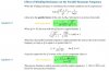
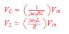
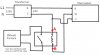
on this series RLC circuit. In a series RLC circuit voltage amplification is given as:
The voltage across the capacitor or inductor is inversely proportional to the resistance. I see a contradiction in
Diver300 's statement. First, he is saying that resistance is large in the given circuit and then he is saying that in such a circuit much more voltage would appear across the capacitor or inductor... At resonance voltage across resistor is just equal to Vin. So, what am I missing here?
Question 2:
In
this post, post #5,
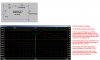
MikeMl posted the following table.
I think I(V1) is the current supplied by the source. I don't understand why phase for I(V1) is -180 degrees. Shouldn't it be 0 degrees?
Question 3:
In
this post, post #6,
MikeMl said.
Who is to say that low Q is not more desirable with respect to ringing and/or transient response than high Q. Both low Q and high Q versions of this circuit could be "better", depending on what the goal is...?
"In electrical circuits, ringing is an unwanted oscillation of a voltage or current.Ringing is undesirable
because it causes extra current to flow, thereby wasting energy and causing extra heating of the components." [Reference:
https://en.wikipedia.org/wiki/Ringing_(signal)]
In a series RLC circuit current is same around the circuit and it is dictated by resistance at resonant frequency so no 'extra current' flow problem. High Q would cause a large voltage appear across capacitor and inductor. But, yes, ringing could be explained in the context of this circuit as voltage spike(s). Do I make sense?
Also, how transient response is affected by high/low Q?
Question 4:
In
this post, post #6, what are those "m^0" symbols on the right side of plot? I have pointed those "m^0"
here.
Question 5:
Near the end of
this post, post #8,
MikeMl asked me the following question.
Do you understand why at much below resonance, V(z) approaches 5V, and much above resonance, it approaches 0V?
V(z) is across capacitor. At low frequencies a capacitor has high reactance but as the frequency increases, its reactance starts decreasing. So, at low frequencies more voltage would appear across the capacitor and at high frequencies low voltage. Correct?
Question 6:
In
this post, post #5,
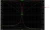
MikeMl used a plot with dB scale.
Please have a
look here.
Solid lines represent voltages.
The dotted lines represent the phases.
1 KHz is resonant frequency and all the voltage appear acoss the resistor, V(x) and phase is 0 degrees. I have marked the voltage V(s), blue mark, and its phase with blue mark circled red. This voltage is 5V.
At resonant frequency V(y) should be 0 V and you can see that it extends toward negative dB scale and this is correct.
V(z) is voltage across the capacitor. At resonant frequency it should be 3.3333 V.
I don't understand how V(x) and V(z) are almost equal low frequencies; for example, look around 100 Hz and above it.
Thank you very much!