Hi,
Could you please help me with the question below?
Please have a look on the
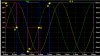
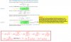
attachment. I'm not sure how they are getting to this final expression. I had thought that perhaps they started with the 'initial expression' and after simplification got this final expression but it looks like I was wrong. You can see below that I tried to simplifyy the initial expression but it ended up to something different from final expression. Thank you!
Note to self:
Q (the “quality factor”), is a measure of how much energy is not lost in a reactive element. The higher the Q, the less energy is lost. Quality factor exist for inductor as well as capacitor. Q_C=Xc/Rc=1/(2*pi*f*C*Rc) and Q_L=X_L/R_w=2*pi*f*L/Rw where Xc=1/(2*pi*f*C) is capacitive reactance, Rc is equivalent series capacitor resistance, X_L=2*pi*f*L and Rw is equivalent series winding resistance. When the resistance is just the winding resistance of the coil, the circuit Q and the coil Q are the same.
Helpful link(s):
https://www.capacitorguide.com/q-factor/

")