PG1995
Active Member
Hi
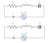
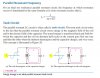
For a series RLC circuit, it is said that at resonance frequency, the individual voltage across capacitor and inductor is equal and larger than the source voltage but 180 degrees out of phase with each which results into net voltage across capacitor and inductor to be zero.
Question:
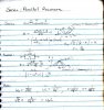
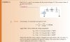
Please have a look here. Don't you think that the voltages founds for R, C, and L are completely wrong?
Note to self:
In mechanical systems, resonance is a phenomenon that occurs when the frequency at which a force is periodically applied is equal or nearly equal to one of the natural frequencies of the system on which it acts. This causes the system to oscillate with larger amplitude than when the force is applied at other frequencies.
Frequencies at which the response amplitude is a relative maximum are known as resonant frequencies or resonance frequencies of the system. Near resonant frequencies, small periodic forces have the ability to produce large amplitude oscillations, due to the storage of vibrational energy.
In other systems, such as electrical or optical, phenomena occur which are described as resonance but depend on interaction between different aspects of the system, not on an external driver.
For example, electrical resonance occurs in a circuit with capacitors and inductors because the collapsing magnetic field of the inductor generates an electric current in its windings that charges the capacitor, and then the discharging capacitor provides an electric current that builds the magnetic field in the inductor. Once the circuit is charged, the oscillation is self-sustaining, and there is no external periodic driving action. This is analogous to a mechanical pendulum, where mechanical energy is converted back and forth between kinetic and potential, and both systems are forms of simple harmonic oscillators.
[Reference: https://en.wikipedia.org/wiki/Resonance]
For a series RLC circuit, it is said that at resonance frequency, the individual voltage across capacitor and inductor is equal and larger than the source voltage but 180 degrees out of phase with each which results into net voltage across capacitor and inductor to be zero.
Question:
Please have a look here. Don't you think that the voltages founds for R, C, and L are completely wrong?
Note to self:
In mechanical systems, resonance is a phenomenon that occurs when the frequency at which a force is periodically applied is equal or nearly equal to one of the natural frequencies of the system on which it acts. This causes the system to oscillate with larger amplitude than when the force is applied at other frequencies.
Frequencies at which the response amplitude is a relative maximum are known as resonant frequencies or resonance frequencies of the system. Near resonant frequencies, small periodic forces have the ability to produce large amplitude oscillations, due to the storage of vibrational energy.
In other systems, such as electrical or optical, phenomena occur which are described as resonance but depend on interaction between different aspects of the system, not on an external driver.
For example, electrical resonance occurs in a circuit with capacitors and inductors because the collapsing magnetic field of the inductor generates an electric current in its windings that charges the capacitor, and then the discharging capacitor provides an electric current that builds the magnetic field in the inductor. Once the circuit is charged, the oscillation is self-sustaining, and there is no external periodic driving action. This is analogous to a mechanical pendulum, where mechanical energy is converted back and forth between kinetic and potential, and both systems are forms of simple harmonic oscillators.
[Reference: https://en.wikipedia.org/wiki/Resonance]
Attachments
Last edited:
")