Man, these articles were awesome, specially the last one, it taught me a lot.
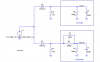
As I understood from the last article, only when the probe's bypass capacitor - Cp -(which is in parallel with the 9Mohm resistor) equals 1/9 of the scope's input capacitance - Cs - then Cs and Cp are connected in series, and therefore as you said, the loading capacitnace that is imposed on the DUT is Cs||Cp which is smaller then Cs.
That is why the 9MHz resistor decrease the capacitance loading ?
only because of the Cp connected to it in parallel?


")