Hi,
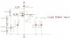
We are investigating getting a fixed 8V3 rail with a cheap opamp as in the attached. (it must source and sink…the opamp’s output current is as in the attached)
Can you confirm that the 4R7 resistor at the output of this MIC6211 opamp makes it stable?
*........................*............................*..............................*.......................*........................
Clearly the 200nF output capacitance adds a pole at 1/(2.pi.RO.CL)
Where:
Ro = opamp output resistance = 125R
CL = Capacitive load = 200nF (Ceramic X7R capacitor)
….This pole is at 63.7kHz.
I would have thought a zero is needed to cancel this pole….hence the 4R7 was added.
The 4R7 (=Rz) adds a zero at 1/(2.pi.Rz.CL) = 169kHz
(The load resistance = 8V3/0.0085A = 976R = RL)
Clearly , there is also a load pole at 1/(2.pi.RL.CL) = 815Hz
There is also an unknown pole added inside the opamp’s internal compensation circuitry. This is going to make it difficult to make out the Bode plot.
When I have all the poles and zeros, I can make out the bode plot and check the gain and phase margin with the 4R7 compensation resistor added.
The pole transfer function is T(s) = 1 / { 1+ j(w/w0)}
The zero transfer function is T(s) = {j(w/w0)} / { 1+ j(w/w0)}
But what are all the pole and zero frequencies?
MIC6211 datasheet
https://ww1.microchip.com/downloads/en/DeviceDoc/mic6211.pdf
(incidentally, the actual voltage across the 200nF output capacitor bank is stable in the prototype circuit we have in the lab…in fact, it is even stable if we increase the output capacitor bank to 51.7uF of ceramic X7R capacitance!!….but we want to be sure)