Continue to Site

Welcome to our site!

Electro Tech is an online community (with over 170,000 members) who enjoy talking about and building electronic circuits, projects and gadgets. To participate you need to register. Registration is free. Click here to register now.

  • Welcome to our site! Electro Tech is an online community (with over 170,000 members) who enjoy talking about and building electronic circuits, projects and gadgets. To participate you need to register. Registration is free. Click here to register now.

Require An Aid For Hearing Aid

Status
Not open for further replies.

leonidus

New Member
Hello friends!!!
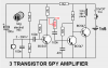
I am doing ckt.3(3 transistor spy amplifier) as project of:-**broken link removed**
I think the 100n cap across the mic. would behave as short even for mid freq..And what it means by "if the 100n across the microphone is removed, the circuit feeds-back almost constantly." Pls. explain.
The last stage is a direct coupled one. So o/p may be above 0ref. & as the spk. is directly connected this may damage the spk..
Also, is the last transistor used as a switch?(since no biasing is used)
Would the direct 1.5V across that one not cause a problem?
While doing a dc analysis, should the 32Ω impedance of the spk. be considered? (or else take it as a short)
I want to make an option for controlling volume. Will a pot do? Where it should be used & of what value? Also a logarithmic/linear? Pls. explain how we decide these parameters(value,type,position)?
I am new to this field. SO, pls. clear my doubts.
Thanx (in advance)!!!:D
 
The link you posted is broken we have nothing to look at.
 
**broken link removed**

The circuit comes from a SPY AMPLIFIER in which more than one million have been made and sold.
You have to build the circuit or buy one from a toy shop for $2.00 rather than ask a lot of questions.
No-one is going to be able to help you as they don't know the gain of the microphone and no "software package" is going to be able to simulate the conditions.
You can change the value of the 30k resistor if you want to improve the gain but, as the text says, you will very quickly run into feedback or motor-boating as the circuit has enormous gain.
The last transistor is not used as a switch. The circuit is an audio amplifier. It is simply a buffer stage to match the output of the second transistor to the low impedance of the earpiece.
A log pot has the effect of appearing to be linear to the ear - that's why they are used.
I wonder if you will ever get around to putting it togher, rather than sitting around cogitating.

Colin Mitchell
TALKING ELECTRONICS
 
Last edited:
The circuit comes from a SPY AMPLIFIER in which more than one million have been made and sold.
You have to build the circuit or buy one from a toy shop for $2.00 rather than ask a lot of questions.
I already know the ckt. is working & in use. As I am building this one I just wanted to clarify my doubts so that in future I should be able to design the projects on my own.
No-one is going to be able to help you as they don't know the gain of the microphone and no "software package" is going to be able to simulate the conditions.
If the gain of the microphone is not known, then how the ckt. designer has decided to use these components shown in the ckt. rather designed the ckt?
I just want to know everything about this ckt. so that if someone asks me anything about this I should be able to explain him.
Thanx colin55 for the reply. Pls. tell me about these things:-
1)I think the 100n cap across the mic. would behave as short even for mid freq..And what it means by "if the 100n across the microphone is removed, the circuit feeds-back almost constantly."
2)The last stage is a direct coupled one. So o/p may be above 0ref. & as the spk. is directly connected this may damage the spk..
3)While doing a dc analysis, should the 32Ω impedance of the spk. be considered? (or else take it as a short)
4)Of what value should the pot be & where it should be placed.Pls. explain how we decide these parameters.
 
When you buy electret microphones by the 100,000 they are batched and you get a specific sensitivity.
The same with transistors. The transistors used in this circuit are surface-mount.

The 100n across the microphone does have an effect on the sensitivity but it has the greatest effect on high frequencies and this is where the feedback occurs.

How can you damage the earpiece on 1.5v???

The pot should be either 25k or 50k and take the place of the 30k.

These things are all derived by intimate knowledge of how the circuit works. That's why you learn electronics.
 
Thank u !!!
I got to know many things.
Just tell me from where the feedback occurs-from any cap?. And what do u mean by "surface-mount".
 
Refer to the website and see the photo of the circuit.

Feedback occurs when the microphone hears the sound reproduced by the earpiece. This is called acoustic feedback.

Feedback also occurs when the microphone detects the ripple produced by the earpiece on the power rail and amplifies it. This is called motor-boating.
 
Surface mount is a way of mounting components so you don't have to drill holes in the PCB (see Wikipedia).

Why do you write in a horrible orange font that's difficult to read?
 
The 100nF capacitor across the mic reduces frequencies above about 1455Hz:
1) The impedance of the electret mic is about 10k ohms at the low current it is fed.
2) The divider of the 1.5k resistor and the 8.2k resistor is 1.27k ohms.
3) The input impedance of the second transistor is about 10k ohms at its very low voltage and current.
4) The total impedance that the 100nF capacitor across the mic sees is 1.1k ohms.
5) The cutoff frequency is 1455Hz. The 47nF capacitor also cuts high frequencies.
Very muffled sound.

A hearing aid does the opposite. It boosts high audio frequencies.
 
Thank u friends for ur replies!!!
AG what do u want to convey thru this:-
A hearing aid does the opposite. It boosts high audio frequencies.
Is this ckt. not working as a hearing aid?
I have an cond. mic. If I use it there in place of the shown one, is there a need to connect a resistor in series with it(1 terminal to supply other to mic) for biasing the mic ?
 
Is this ckt. not working as a hearing aid?

No.
It severely cuts high audio frequencies. Deaf people usually need to have the high audio frequencies boosted.

I have an cond. mic. If I use it there in place of the shown one, is there a need to connect a resistor in series with it(1 terminal to supply other to mic) for biasing the mic ?
A condenser mic is very expensive. It needs a 48V power supply.
Use an inexpensive electret mic that has a permanent high voltage charge and has a FET transistor built inside it.
 
Quote:
Originally Posted by leonidus View Post
Is this ckt. not working as a hearing aid?

No.
It severely cuts high audio frequencies. Deaf people usually need to have the high audio frequencies boosted.
Then why this ckt. is called a "HEARING AID".

I am going to connected the pot in place of 30k as told by Collin55. I would connect it as: left terminal to gnd, middle one to the collector of 1st transistor & right one to 100n cap.. Am I correct?
 
Am I correct with connections:-
I would connect the pot in place of 30k(as told by Collin55) as: left terminal to gnd, middle one to the collector of 1st transistor & right one to 100n cap..

Please help!!!:confused:
 
Am I correct with connections:-
I would connect the pot in place of 30k(as told by Collin55) as: left terminal to gnd, middle one to the collector of 1st transistor & right one to 100n cap..

Please help!!!:confused:
Your idea would short the collector to ground without adding another coupling capacitor.
Simply use the potentiometer as a variable resistor like this:
 

Attachments

  • spy amplifier.PNG
    spy amplifier.PNG
    10.3 KB · Views: 258
Since a cap behave as a short ckt. for mid freq. range, then even though I use it before the pot(with my connections), the collector would get gnded?
Or else, how it works?

The last transistor is not used as a switch. The circuit is an audio amplifier. It is simply a buffer stage to match the output of the second transistor to the low impedance of the earpiece.
We use a common collector config. for impedance matching( ri/p very large & ro/p in Ω). Whereas here, in the 3rd stage CE config. is used( ri/p= 1k-3kΩ & ro/p=40k-80kΩ). Why?


Since a cap behave as a short ckt. for mid freq. range, then even though I use it before the pot(with my connections), the collector would get gnded?
Or else, how it works?

??????????????????


We use a common collector config. for impedance matching( ri/p very large & ro/p in Ω). Whereas here, in the 3rd stage CE config. is used( ri/p= 1k-3kΩ & ro/p=40k-80kΩ). Why?

The reason why a common-emitter configuration has been used is because we only have 1.5v rail and this is very little voltage to play with.
We could have used common collector (emitter follower) for the output transistor but since the third transistor has to be connected to the collector of the second transistor, we have to look at the voltage swing on the collector of the second transistor.
This voltage swing is not very much and the transistor is sitting at approximately mid-rail. Suppose this is about 0.7v This means the swing of the emitter of the third transistor will be 0.7v less than the swing of the collector of the second transistor. If we put headphones onto the emitter we will get almost no output.
That's why a common emitter stage has been used for the output.
The collector of the second transistor will swing nearly 1v and thus the output transistor will swing almost 1.5v but it will have about 100 times more “current” to drive the earpiece and achieve the greatest volume.
 
I got what u told Collin.
1) How much max. voltage supply can I give to the ckt?
2) Since a cap behave as a short ckt. for mid freq. range, then even though I use it before the pot(with my connections), the collector would get gnded?
Or else, how it works?
3) While doing a dc analysis, should the 32Ω impedance of the spk. be considered? (or else take it as a short)
4) I want to test my mic. whether it is converting sound to electrical signal- a resistor of about 1k in series with mic & o/p(on CRO) across the resistor???
Please ans. all questions.
 
I simulated it. Its frequency response is horrible.
It is flat from about 180Hz to about 185Hz.
Its high frequencies are down -3dB at about 250Hz and 2kHz is down -22dB.

I didn't bother looking at its distortion.
 

Attachments

  • sim spy amplifier.PNG
    sim spy amplifier.PNG
    30.5 KB · Views: 257
You cannot increase the voltage. The circuit has so much gain that any increase in voltage will cause self-oscillation. This is because the output is connected to the input via the power rail.
There is already 3 components in the circuit that are needed to reduce the possibility of feedback and any increase in supply voltage will increase the gain of the stages to such an extent that motor-boating will occur.

Where do you get the idea that a capacitor acts as a "short circuit" at mid-frequency?

The output of an electret microphone is only about 20mV. You can measure this across the load resistor. The load resistor should be 10k for 1.5v supply.
 
Status
Not open for further replies.

Latest threads

New Articles From Microcontroller Tips

Back
Top