Continue to Site

Welcome to our site!

Electro Tech is an online community (with over 170,000 members) who enjoy talking about and building electronic circuits, projects and gadgets. To participate you need to register. Registration is free. Click here to register now.

  • Welcome to our site! Electro Tech is an online community (with over 170,000 members) who enjoy talking about and building electronic circuits, projects and gadgets. To participate you need to register. Registration is free. Click here to register now.

Require An Aid For Hearing Aid

Status
Not open for further replies.
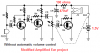
I am using BC547B transistors for Q1,Q2. So, as told by u I would connect the 62k resistor(R2).
Thanx for correcting about the pot which was by mistake taken as 2k.
U considered 1V while calc. for 62kΩ whereas 1.5V for the 1.1MΩ.Why?
As there would be some drop across R8, I think the voltage of battery for Q1 Q2 available is nearly 1V.:confused:
As the ckt. is modified, are the values of other components also changed?
The stereo Jack socket has 3pins- 1 long one & 2 short ones facing each other. So, as told "Please note the stereo output Jack socket (J1) connections: only the two inner connections are used, leaving open the external one. In this way the two earpieces are wired in series, allowing mono operation and optimum load impedance to Q4 (64 Ohm)." the 2 short ones are to be connected leaving the long one. Also any of the 2 short can be connected to any point(1.5V/C of Q4). Is it correct?
 
U considered 1V while calc. for 62kΩ whereas 1.5V for the 1.1MΩ.Why?
The original circuit has the bias resistors connected to +1.5V which is a very poor way to bias a transistor but is the only simple way to have the automatic volume control.
My circuit has the biasing resistor connected to the collector of the transistor which is at about 1V so it has less voltage across it so it needs to be a lower value. It provides negative DC feedback.

As there would be some drop across R8, I think the voltage of battery for Q1 Q2 available is nearly 1V.:confused:
No.
R8 is only 100 ohms. A current of 5mA would cause a voltage drop of 0.5V. The current of the mic is about 0.1mA, the current of Q1 is 0.1mA and the current of Q2 is 0.1mA. So the total current in R8 is only 0.3mA and its voltage drop is only 0.03V.

As the ckt. is modified, are the values of other components also changed?
No.

The stereo Jack socket has 3pins- 1 long one & 2 short ones facing each other. So, as told "Please note the stereo output Jack socket (J1) connections: only the two inner connections are used, leaving open the external one. In this way the two earpieces are wired in series, allowing mono operation and optimum load impedance to Q4 (64 Ohm)." the 2 short ones are to be connected leaving the long one. Also any of the 2 short can be connected to any point(1.5V/C of Q4). Is it correct?
I think it is a stupid way to connect headphones since they will be out-of-phase.

Speaking of headphones phase, yesterday I looked for Surround Sound in Google. This link provides sound in headphones that appears behind you: **broken link removed**
 
Last edited:
I am using a mobile earphone set for connecting to the device(to avoid acoustic feedback). So, I am using a 3.5mm jack for connection. Tell me the connections told by me are correct or wrong?
In the original ckt, its given that the ckt. draws typically a current of 7.5mA.
Then the voltage drop across R8 would be 7.5m*100=0.75V So for the 1st 2 stages .75V is available. If β=150,say, Ib=6.48*10^-8 whereas Ic=9.72*10^-6 , how so less? And is this the way u calc.?
Also, how the current of mic would affect R8? It is affected by the 1.5Vdc battery, isn't it?
For what purpose R1 is used? There is no need for biasing the mic.
 
Electret mic has in built FET buffer circuit! R1 determines the output impedance and is a current limiter too.
 
I am using a mobile earphone set for connecting to the device(to avoid acoustic feedback). So, I am using a 3.5mm jack for connection. Tell me the connections told by me are correct or wrong?

The circuit is designed for a load of 64 ohms (two 32 ohm earsets in series) which causes them to be out-of-phase which is wrong. The circuit puts DC in the earphones which is also wrong and wastes a lot of battery power.
I don't know if your earphones are mono or stereo and i don't know if each ear is 32 ohms.

In the original ckt, its given that the ckt. draws typically a current of 7.5mA.
Then the voltage drop across R8 would be 7.5m*100=0.75V So for the 1st 2 stages .75V is available. If β=150,say, Ib=6.48*10^-8 whereas Ic=9.72*10^-6 , how so less? And is this the way u calc.?

No.
The entire circuit draws 7.5mA. The output transistor draws about 7.2mA (when its load is 64 ohms), the electret mic draws about 0.1mA, Q1 draws 0.1mA and Q2 draws 0.1mA.

Also, how the current of mic would affect R8? It is affected by the 1.5Vdc battery, isn't it?
I do not know what you are asking.

For what purpose R1 is used? There is no need for biasing the mic.
The mic is a condenser electret type. It has a plate beside its diaphragm that is permanently charged with 48V and has a FET transistor to detect the small change of voltage as the diaphragm moves by sounds. The FET transistor is powered from R1.
 
The circuit is designed for a load of 64 ohms (two 32 ohm earsets in series) which causes them to be out-of-phase which is wrong. The circuit puts DC in the earphones which is also wrong and wastes a lot of battery power.
I don't know if your earphones are mono or stereo and i don't know if each ear is 32 ohms.
TO avoid these prob.s what should I do? Will U pls. explain how the earsets will be out-of-phase?
Also since spk. is connected b/w 1.5V & C of Q4, is there a dc in earphones?
I use the earphones to listen music from pc. I don't know about its specifications. All I know is it needs a 3.5mm jack socket.
The mic is a condenser electret type. It has a plate beside its diaphragm that is permanently charged with 48V and has a FET transistor to detect the small change of voltage as the diaphragm moves by sounds. The FET transistor is powered from R1.
But in that 3 transistor spy amplifier ckt., the mic was not with a resistor. Why?
 
But in that 3 transistor spy amplifier ckt., the mic was not with a resistor.

My 3 Transistor Spy Amplifier has a load resistor for the microphone.

Can you just get on with building the circuit and stop wasting everyone's time.
 
TO avoid these prob.s what should I do?

Find a circuit that does not have these problems. I would use an LM386 little amplifier IC like they do at www.headwize.com .

Will U pls. explain how the earsets will be out-of-phase?
Normally, both earsets are connected in parallel in-phase so that the diaphragms move in the same direction. But each earset has one terminal connected to ground. Therefore when they are connected in series they are out-of-phase and the diaphragms move in opposite directions which is wrong. The circuit should be able to drive both earsets in parallel.

Also since spk. is connected b/w 1.5V & C of Q4, is there a dc in earphones?
Yes.
The DC causes the diaphragms to be forced off-center which might cause distortion and might damage the headphones.

I use the earphones to listen music from pc. I don't know about its specifications. All I know is it needs a 3.5mm jack socket.
It is simple to measure the resistance of each earset. Mine measure 18 ohms for each ear so each has an impedance of about 22 ohms.

But in that 3 transistor spy amplifier ckt., the mic was not with a resistor. Why?
It uses an electret mic like all the other circuits. I don't know why it is powered from a voltage divider instead of just a single resistor.
 
Colin55
Can you just get on with building the circuit and stop wasting everyone's time.
Is asking questions & getting ur mistake corrected wasting time? I don't thinks so. U & many others know many things as u all have spend time with these things. I am new to these things & interested in this subject. As I have told u earlier also, I want to increase my knowledge & this forum is meant for that only. Am I correct or not? Else many newbies wouldn't be joining these forums asking doubts.
Normally, both earsets are connected in parallel in-phase so that the diaphragms move in the same direction. But each earset has one terminal connected to ground. Therefore when they are connected in series they are out-of-phase and the diaphragms move in opposite directions which is wrong. The circuit should be able to drive both earsets in parallel.
So, should I connect the jack taking gnd common & wires(from C & 1.5V) to the other 2 terminals of jack? Also, is the long terminal gnd & other 2 short ones for other connections?
Thanx AG for the explanation.
 
Is asking questions & getting ur mistake corrected wasting time? I don't thinks so. U & many others know many things as u all have spend time with these things. I am new to these things & interested in this subject. As I have told u earlier also, I want to increase my knowledge & this forum is meant for that only. Am I correct or not? Else many newbies wouldn't be joining these forums asking doubts.
So, should I connect the jack taking gnd common & wires(from C & 1.5V) to the other 2 terminals of jack? Also, is the long terminal gnd & other 2 short ones for other connections?
Thanx AG for the explanation.
Most of us are happy to explain things to you.

The very simple circuit is designed for a 64 ohms load. It might work with a 32 ohms load but then the battery current will be almost doubled even when it is not playing sounds.

You can try it with both of your earsets connected in parallel.
Instead of talking about "the long terminal" and "the terminals that face each other", here is a sketch of the stereo plug and jack:
 

Attachments

  • Stereo headphones plug and jack.PNG
    Stereo headphones plug and jack.PNG
    54.3 KB · Views: 174
Thanx for ur support!!!:)
If I connect in parallel the impedance will be 16Ω. So, 4 times more current will be drawn. The original connection may be preferred??????
Sorry, by mistake I called the socket as jack. I was talking about the 2 small terminals & 1 long one of socket. Is the long one gnd(common) & other 2 for right & left? Can any of right/left be connected to any of these of sockets?
 
It doesn't really pull the transistor up. This is wrong wording. I didn’t refer to the circuit.
Think of the output transistor as being biased by the 2k2 base resistor.
The 2k2 turns the transistor ON. The current flowing through the 2k2 will be multiplied about 70-100 times (due to the gain of the transistor) and this will determine the maximum current able to flow through in the collector circuit. We now look at the resistance of the load in the collector circuit and see if this current will flow.
The middle transistor operates as a "robbing device."
It turns on when audio is detected and robs the output transistor of some of the base current and this is how the output transistor is turned off.
 
For any ripple in 1.5V battery C5 will act as a short. What does R8 do there?
What if I remove R8?
 
R8 and C5 are a filter. C5 is a much better filter when R8 is there. The high flucuating current in the output transistor causes the +1.5V to jump up and down a lot and R8 and C5 filter it so the +1.47V to the mic and the preamp transistors is smooth.
 
I simulated the RED Circuits' Amplified Ear circuit without the automatic volume control. The low frequency response drops below about 200Hz and is flat to above 100kHz. The gain is about 38dB which is almost 100.

The distortion at full output is mostly even harmonics and is not too bad.
 

Attachments

  • sim-amplified ear1.PNG
    sim-amplified ear1.PNG
    42.6 KB · Views: 188
  • sim-amplified ear2.PNG
    sim-amplified ear2.PNG
    25.7 KB · Views: 183
R8 and C5 are a filter. C5 is a much better filter when R8 is there. The high flucuating current in the output transistor causes the +1.5V to jump up and down a lot and R8 and C5 filter it so the +1.47V to the mic and the preamp transistors is smooth.
If R8 is removed full 1.5V is available to the mic,Q1,Q2 & also C does the filtering.So, there is no need for R8?????????
What if it is removed?
 
Status
Not open for further replies.

Latest threads

Back
Top