Continue to Site

Welcome to our site!

Electro Tech is an online community (with over 170,000 members) who enjoy talking about and building electronic circuits, projects and gadgets. To participate you need to register. Registration is free. Click here to register now.

  • Welcome to our site! Electro Tech is an online community (with over 170,000 members) who enjoy talking about and building electronic circuits, projects and gadgets. To participate you need to register. Registration is free. Click here to register now.

Red laser driver with a single cell

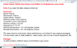
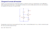
Hi guys, i'm new. My name is Aldo and as my 1th post I want to show you an interesting argoment that can teach you how to make a laser driver compatible for any type of laser diode... You just have to change the resistor actoss R2 to set output current: https://www.merghart.com/p/27/Two-Transistor-laser-current-source

So today i'm trying to test if this driver is working, and i've seen a youtuber making the same circuit, but he is using 2 PNP transistors instead 2 NPN... Anyway the circuit is the same and it's cleary visible at the second 00:00:50 see the following video here:


What i can't understand is: why he added 2 capacitors (which are not included on the drawn scheme)??? See minute 00:01:50 ???

NOW I HAVE 2 SERIUS PROBLEMS:
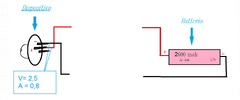
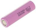
1) I need to run a red laser that has a drop around 2.3-2.7 volt at 0,82 A, and i want to use """A SINGLE CELL""" (Li-ion 3,7... 18650 battery size). (see my attached files). The reason is because i don't have much space for my project... I want to make a compact laser using a simple flashlight... so i must reduce the space and use 1 single cell.

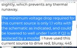
NOTE = I don't want to use 2 RCR because i want it can endure more with a 18650. So please understand my point... What i'm trying to do is to make this driver more effective... So i'm trying to make the dropout, """lower" than 1,1 volt, and as the post said, """it is cleary possible to reduce the voltage drop by using a simple mosfet...""" The problem is that i don't know wich mosfet is the best for my laser diode and i don't know where to connect to this circuit. So i don't even know which is the formula used if i substitute the Transistor Q2 with a mosfet.

2) The second problem is that since the guy on this video added 2 capacitors i started to have a lot of doubth about.. (i must add more components)... And now, I don't know where to connect these 2 capacitors to this simple circuit, and i don't know even the value of these 2 capacitors.

-------------------------------------------------------------------------------------------------------------

Now, could you help me by drawing the circuit and show me cleary how to use the mosfet instead the BJT and where to add these 2 capacitors please? I'm getting crazy and no one help me :(
Thanks you.
 

Attachments

  • Immagine7.png
    Immagine7.png
    131.6 KB · Views: 123
  • 358745879_594175472836486_7488274784789421995_n.png
    358745879_594175472836486_7488274784789421995_n.png
    251.6 KB · Views: 121
  • battery.jpg
    battery.jpg
    4 KB · Views: 104
  • dropout.jpg
    dropout.jpg
    245.4 KB · Views: 132
  • sorgente1.png
    sorgente1.png
    75.8 KB · Views: 125
That particular constant current configuration CANNOT be achieved with Mosfets.
Now, there are specialized IC drivers which might fit your requirements. But the question begs, would you be willing to consider higher complexity and cost?
 
I have an idea that may work, but it will be a couple of days before I get chance to do a proper drawing of it.

Concept:
PNP transistor, emitter to battery V+, collector to laser diode +.

Laser diode - to low value sense resistor, to 0V.

A low voltage opamp such as a TL9721 comparing the voltage across the sense resistor (+ in) to a preset with series resistor (- in) connected across a diode (biased via another resistor to V+) to give an adjustable low reference, probably in the 0.1 to possibly 0.2V range.

Opamp output to the transistor base via an appropriate limiting resistor, also a base-emitter resistor to guarantee full shut off.

It would likely need filtering or slew rate limiting for stability, but I think with an appropriate sense resistor to get ~100mV at the required current, a very low drop-out voltage should be possible.
But is it possible to reach 700 mw of power? An Opamp would be better of course.. But they should be through hole components because you can not test on breadboard by using smd components... And afrer i assembled i must pray that it works.. otherwise ill just damge the diode... I can use a simulator but it wont never be sure untill you test it in real board. I think its better to use through hole components whatever is the best way.

Let me know please if you can make a better circuit by using simple components or you can just substitute some component to get a better performance.
Update me Thanks.
 
I need to run a red laser that has a drop around 2.3-2.7 volt at 0,82 A
One that powerful could easily blind people. What will you use it for?
I want to make a compact laser using a simple flashlight.
Waving it around as a flashlight would be very dangerous. Even the light reflected off objects could be harmful.
 
One that powerful could easily blind people. What will you use it for?

Waving it around as a flashlight would be very dangerous. Even the light reflected off objects could be harmful.
There are a lot of dangerouse laser pointers online, more dangerouse than the laser that i'm trying to make. If my plan was really to hurt someone i was looking for a laser already assembled and ready to use... But what i'm looking for is just to build and learn how to make a better project by using simple components and cheap as you can use for general purpose like engraving and laser cut. This is not even the most powerfull laser on the market... Of course this could be a class IV laser so it's still dangerouse but i already have the licence and i work by using lasers, so i know how to manage this diode and i always wear glasses.
 
I have an idea that may work, but it will be a couple of days before I get chance to do a proper drawing of it.

Concept:
PNP transistor, emitter to battery V+, collector to laser diode +.

Laser diode - to low value sense resistor, to 0V.

A low voltage opamp such as a TL9721 comparing the voltage across the sense resistor (+ in) to a preset with series resistor (- in) connected across a diode (biased via another resistor to V+) to give an adjustable low reference, probably in the 0.1 to possibly 0.2V range.

Opamp output to the transistor base via an appropriate limiting resistor, also a base-emitter resistor to guarantee full shut off.

It would likely need filtering or slew rate limiting for stability, but I think with an appropriate sense resistor to get ~100mV at the required current, a very low drop-out voltage should be possible.
Have you find something? Let me know please.
 
Does the laser really need a constant current drive? If the cell voltage drops from 4.2V to 3.5V in use and the laser voltage drop is in the 2.3-2.7V range, current limiting using a simple dropper resistor might be adequate.
 
Does the laser really need a constant current drive? If the cell voltage drops from 4.2V to 3.5V in use and the laser voltage drop is in the 2.3-2.7V range, current limiting using a simple dropper resistor might be adequate.
Going back to CD player lasers, they are EXTREMELY critical about the current they are supplied, and easily killed by only a small overload. So I would expect it's a good idea to run a laser diode with a fairly constant current.
 
Ok. I wasn't aware the current was so critical.
 
This should probably work, looking at the component specs?

C4 & R5 will probably need adjusting for optimum response and stability over the working voltage range. R3 possibly linked out & R4 removed.

View attachment 142373
Umm. it's interesting.. But i was thinking about a configuration with a TL431 instead an unstable zener diode for temperature changes. And an NPN like D882 instead a Mosfet. Have you tryied it? Is the same configuration??
 
instead an unstable zener diode
No zener, it's a 1N4148 signal diode, used to give around 0.6V
If it were thermally connected to the laser heatsink it could give some thermal compensation?

You could use a voltage reference with an appropriately adjusted divider to still give a suitable reference voltage range to the opamp.
I'd go for a 1.25V type or thereabouts, so there is less variation in bias current over the battery voltage range.

A P-channel MOSFET could work provided it's ON resistance is low enough at around 3V gate-source voltage.
They are difficult to find in conventional packages for prototyping, while the device I chose has high gains and is quite cheap, in an easy to use TO-220 package.
 
No zener, è un diodo di segnale 1N4148, utilizzato per dare circa 0,6 V
Se fosse collegato termicamente al dissipatore laser, potrebbe fornire una compensazione termica?

È possibile utilizzare un riferimento di tensione con un divisore opportunamente regolato per fornire comunque un intervallo di tensione di riferimento adeguato all'amplificatore operazionale.
Sceglierei un tipo da 1,25 V o giù di lì, quindi c'è meno variazione nella corrente di polarizzazione nell'intervallo di tensione della batteria.

Un MOSFET a canale P potrebbe funzionare a condizione che la sua resistenza ON sia sufficientemente bassa a una tensione gate-source di circa 3 V.
Sono difficili da trovare nei pacchetti convenzionali per la prototipazione, mentre il dispositivo che ho scelto ha guadagni elevati ed è abbastanza economico, in un pacchetto TO-220 facile da usare.
I have a question. In case I wanted to use a linear circuit instead of a switching one, is there any other option that could work the same way?

For example, about the circuit i posted "dual transistor", you tried to simulate with a germanium transistor (Q1) and an KSD1691 (Q2). Can it work?
 
The circuit I suggested is a purely linear one?
it's good. Ill make yours since now... But I was just looking for an alternative about the 2 bjt transistors... because i already have lots of pcb to solder and i don't want to throw now. They already have the rail for dual bjt config.

Tell me if it can work with KSD1691 (Q2) and some germanium transistor at (Q1). i'm just trying to make the total dropout lower than 0,5 volt. Tell me which components can i use for my old version circuit. Because i will replace with a new circuit the next month.
Thanks
 
The two-transistor version is not capable of giving a really low voltage loss, as the sense resistor must have the lower transistor base-emitter voltage across it to work.

A germanium one would reduce it to possibly 0.3V at that point.

R1 would need to be around 100 Ohms or possibly less, to ensure Q2 conducted sufficiently, with the KSD1691 and a low battery.
Means. Have you simulate how much would be the Total circuit drop out in this way? 0,3 of the germanium transistor + 0,1 of the KSD1691. Total = 0,4 drop ... Is It correct or im missing something? If you confirm before i buy because i Need to make sure it Will work. The important Is that Is working.. i Need to wait 1 month before use your version... For now i Just have to improvvise with 2 NPN.
If you find a Better component instead germanium transistor or instead Q2 It Is very important for me. But i think i found the best already i Just want a confirm because i can not afford to buy and if i can not use
 
It's all down to the characteristics of the transistors, and also as that circuit has no adjustment, getting the exact right value for the sense resistor.

Most germanium transistors are now decades old and their characteristics vary wildly; I bought a batch of ten of the same type a few years ago to repair a piece of 70s industrial gear, and every one was different; some of them barely worked.

It's more chance than design with things like that..

I have no idea how stable the base-emitter voltage would be, so how good the current regulation; not very, I suspect...

Edit:

Data for (what used to be) a common NPN germanium transistor:
 
Last edited:

Latest threads

New Articles From Microcontroller Tips

Back
Top