Continue to Site

Welcome to our site!

Electro Tech is an online community (with over 170,000 members) who enjoy talking about and building electronic circuits, projects and gadgets. To participate you need to register. Registration is free. Click here to register now.

  • Welcome to our site! Electro Tech is an online community (with over 170,000 members) who enjoy talking about and building electronic circuits, projects and gadgets. To participate you need to register. Registration is free. Click here to register now.

Newbie question - basic simulation with amplifier AD620 which necessitate hours to be performed

phl_FR

New Member
Hi !

I'd like some help to debug my simulation, please.

I've probably made a mistake because when I launch the simulation, the calculation lasts hours instead of a few seconds.
I've been trying for hours to understand what is wrong but I still haven't found the reason of this problem.

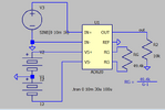
Here on the screenshot, I've used the following parameters :
signal input : sin wave of 1V amplitude, 0V DC and 50 Hz frequency ;
the gain is supposed to be G = 2 (1+ 49,4K/49400).


question forum pbm ad620 simulation LTspice.PNG


Thanks in advance.
 
Hi

1. Edit the ad620.cir model file.

Find this line (approx #112):
L1 45 46 1E-6

Change to:
L1 45 46 1E-6 IC=0

2. Add a small serial resistance to all voltage sources (100m ohms).

3. Be aware the value specified for a sine voltage source is a Peak value. To specify an RMS value, specify the product of the Peak value multiplied by 1.414.

1701370391938.png
 
Last edited:
Thank you very much eTech and danadak.

I've applied the advices. I think I have understood the goal of writing "IC=0" in the circuit file : it sets an initial condition and may reduces substantially the iterations that LTspice computes.
Dealing with the serial resistance 100 ohms with the voltage source : is it usefull for simulation ? I imagine it usefull in case of short circuit, but I'm not sure.

The answer of danadak made me smile because the final prototype's goal is to associate the AD620 (amplifier) to a AD536 (a chip which convert a signal in a RMS value.

My association of the 2 circuits on LTspice has generated errors that I have never been able to solve.

I'll try to study it again in the following days.
 
This is wrong
1703092732127.png


This is correct
1703092784714.png
= 2

If you want to input 1Vrms then specify 1rms not 1 which is pk.
 
Specifying a realistic Rs for any voltage source makes sense when significant voltage drop is expected from load pulses and valid initial conditions for V(C) and I(L) for transient startup, but has no effect on steady state.
 
Hi

1. Edit the ad620.cir model file.

Find this line (approx #112):
L1 45 46 1E-6

Change to:
L1 45 46 1E-6 IC=0

2. Add a small serial resistance to all voltage sources (100m ohms).

3. Be aware the value specified for a sine voltage source is a Peak value. To specify an RMS value, specify the product of the Peak value multiplied by 1.414.

View attachment 143484
When I initially ran the sim, without your recommended changes, I got a couple of random spurious large voltage spikes. After making the changes, it ran great. Just for grins, I removed the 100mohm resistors, and it still runs great.
I'm not saying it's not a good idea. Just sayin'. :)
I did have to start saving data at around 30us to avoid a large negative output spike at startup.
 
Here on the screenshot,
Normally the assigned pin numbers on the schematic part symbol are for the part package, not node numbers in its model file.
The function for each pin is also usually shown.
 
Normally the assigned pin numbers on the schematic part symbol are for the part package, not node numbers in its model file.
The function for each pin is also usually shown.
This happens when you instruct LTSpice to automatically create a symbol from the .cir file. I encountered the same thing when I first ran the sim, so I modified the symbol. See attached files.
 

Attachments

  • AD620 test.PNG
    AD620 test.PNG
    13.4 KB · Views: 61
  • AD620 test.asc
    1.2 KB · Views: 58
  • ad620.zip
    1.9 KB · Views: 64
Is there a way to do that besides multiplying the specified source voltage by √2?
No not on the generator for LTspice, although Falstad supports it directly.
But it supports it on MEAS. command.

.MEASURE -- Evaluate User-Defined Electrical Quantities
the .MEAS statement operates over the entire range of data. The types of measurement operations that can be done over an interval are

KeywordOperation performed over interval
AVGCompute the average of <expr>
MAXFind the maximum value of <expr>
MINFind the minimum value of <expr>
PPFind the peak-to-peak of <expr>
RMSCompute the root mean square of <expr>
INTEGIntegrate <expr>
 
"Automatic Symbol Generation
When editing an ASCII netlist that contains subcircuit definitions, you place the cursor on the line containing the name of the subcircuit, right click, and execute context menu item "Create Symbol." For most users, this is the only method you should ever consider for adding third-party models defined as subcircuits since all the details are handled for you."

Upon running

1707100540051.png


also

1707100687441.png


Located in AD620.asy was
SYMATTR ModelFile C:\Users\rmaxh\AppData\Local\LTspice\lib\sub\ad620.cir

which resulted in error above shown below

XU1 N001 0 N003 N004 out 0 N002 N005 AD620
V1 0 N004 12
V2 N003 0 12
V3 N001 0 SINE(0 10m 1k)
RG N002 N005 49.4k
R2 out 0 10k
.tran 0 10m 30u 100u
* G-1
* RG =
* 49.4k
.lib C:\Users\rmaxh\AppData\Local\LTspice\lib\sub\ad620.cir
.backanno
.end
 

Attachments

  • 1707100668439.png
    1707100668439.png
    9.6 KB · Views: 55
Last edited:
1707110281779.png


Weird!!

- any load more than +25 uA causes a glitch and makes the sim. crawl really slow.

Change RG or R2 load > 25uA , same result. some are 0 risetime glitches
1707137759839.png
 
Last edited:
When I initially ran the sim, without your recommended changes, I got a couple of random spurious large voltage spikes. After making the changes, it ran great. Just for grins, I removed the 100mohm resistors, and it still runs great.
I'm not saying it's not a good idea. Just sayin'. :)
I did have to start saving data at around 30us to avoid a large negative output spike at startup.

But they shouldn't be removed. All supply voltage sources have some resistance.
Just sayin' ;)
 
"Automatic Symbol Generation
When editing an ASCII netlist that contains subcircuit definitions, you place the cursor on the line containing the name of the subcircuit, right click, and execute context menu item "Create Symbol." For most users, this is the only method you should ever consider for adding third-party models defined as subcircuits since all the details are handled for you."

Upon running

View attachment 144380


also

View attachment 144382

Located in AD620.asy was
SYMATTR ModelFile C:\Users\rmaxh\AppData\Local\LTspice\lib\sub\ad620.cir

which resulted in error above shown below

XU1 N001 0 N003 N004 out 0 N002 N005 AD620
V1 0 N004 12
V2 N003 0 12
V3 N001 0 SINE(0 10m 1k)
RG N002 N005 49.4k
R2 out 0 10k
.tran 0 10m 30u 100u
* G-1
* RG =
* 49.4k
.lib C:\Users\rmaxh\AppData\Local\LTspice\lib\sub\ad620.cir
.backanno
.end
Hi Tony,
The zip file, as you apparently know, contains AD620.cir and AD620.asy. I created the .asy file for my own convenience, so the schematic would make more sense to me. I posted what I had done as an explanation to crutschow about the weird AD620 symbol in the OP's schematic.
I'm sure you know that you could have edited AD620.asy to modify the SYMATTR line to reflect the location of YOUR AD620.cir file.
In retrospect, I should have let crutschow continue to wonder why the symbol was weird. It would have saved both you and me a lot of time. :)
Thanks, no sweat for me on the edit to make it work.
But why does it simulate oscillations this low threshold of load current?
That seems wrong.
 

Attachments

  • AD620 test2.zip
    565 bytes · Views: 57
Last edited:

Latest threads

New Articles From Microcontroller Tips

Back
Top