Continue to Site

Welcome to our site!

Electro Tech is an online community (with over 170,000 members) who enjoy talking about and building electronic circuits, projects and gadgets. To participate you need to register. Registration is free. Click here to register now.

  • Welcome to our site! Electro Tech is an online community (with over 170,000 members) who enjoy talking about and building electronic circuits, projects and gadgets. To participate you need to register. Registration is free. Click here to register now.

Quick question on 16F628A

Status
Not open for further replies.
Great to see you got there Al, sometimes another pair of fresh eyes helps.

Hope you guys enjoy the take-away.

Regards.
 
hi Al,
Reply email from Jose Pito, he will correct the Jumbo circuit diagram on his Site as soon as possible. [4050 IC version]

E.
 
Last edited:
that is encouraging to know. perhaps i made a comment that the sch was theoretical or some such thing.

here is the comment under quote"This schematic is only a sample"
 
Last edited:
i remember that

my earlier post should have read" he made a comment.....
not me.
 
Last edited:
Hi Al (and gang),

Just wanted to share a possible paper silkscreen layout for the MIC5891 version "Big Clock" circuitry on a cheapie $4 Radio Shack 276-147 proto' board (11.4x16.0cm). I still have to place some components in the power supply section and I have to figure out where to place four diodes for the switch matrix. I wish I could get a little better spacing on the display too but all in all it doesn't look too bad.

Happy Holidays.

Cheerful regards, Mike

big-clock-png.58989
 

Attachments

  • Big Clock.png
    Big Clock.png
    81.6 KB · Views: 1,040
Last edited:
Hi Mike,

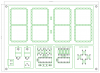
Thats looking neat! A lot neater than mine, saying that I purposely put my LEDs and circuitry on separate boards so I could keep the footprint of the clock just a little bigger than the actual digits.

I also used Proto board, the kind with just little square copper pads, which I find easier to "blob" two together on than the Protos with the round pads, which makes joining the strings of LEDs easier.

I have now got the clock bug pretty bad and am just making the prototype segments for my next one with digits being about 10" high. Your suggested IC should be ideal for it as the segments only have 3 LEDs in them and draw 80mA at 12v. I just can't decide whether to go with Red, Blue or Green ones.

I had one mad scientist moment where I was considering RGB switchable segment colour but when I came to my senses and realised all the extra wiring involved I decided against it! hehehe

Anyway I can't wait to see the full design working with your IC and code so keep up the good work.

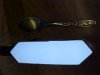
Edit. Here is a photo of one of my segments lit by white LEDs, its hard to get good shots of them with the camera, the spoon beside it is a teaspoon.

Al
 

Attachments

  • MVC-503F.JPG
    MVC-503F.JPG
    40.6 KB · Views: 217
Last edited:
Hi guys,

Sorry to ressurrect this thread but I have another related weird problem!

I have just made a second circuit the same as my first jumbo clock circuit the only difference being that I have replaced the small 2N3906 PNPs with larger TIP125 PNPs and neatened up the links a bit.

I always test points for correct voltage without the ICs in when building and all seemed ok, but when I actually tried the board I got something strange happening. All the segments are on constantly except the colon which is flashing happily as it should!

Now I just can't figure out what would put all the segments on but still flash the colon.

If I had burned another PIC and used new ICs all round then I would be suspicious of them but I have used the original clocks PIC and ICs, and they are fine when in the original board. I have put them back in the old one and it works happily.

So it must be the board but I have looked and looked but can't see the trouble. Can anyone suggest what to look at or test specifically for this strange problem?

Could substituting the larger transistors be a cause? BTW I have rejigged the board to accept the different pinouts of the transistors.

Some things I am sure about.
1) the micro is running - flashing colon shows this.
2) the LEDs are all fine - I'm testing the new board on the old LED setup.
3) all the ICs are ok - when in the old board
4) the power source is ok - same for both boards

So any ideas guys

Thanks Al
 
hi Al,
The TIP125 is a Darling transistor and may not be being switched off fully.
 
hi Al,
The TIP125 is a Darling transistor and may not be being switched off fully.

Hi Eric,

I realised it was a darlington but didn't think it would be a problem mate.

Any ideas on how to prove the theory?

But if it is the problem then how come the colons work ok? puzzled!

Regards Al
 
Hi Eric,

I realised it was a darlington but didn't think it would be a problem mate.

Any ideas on how to prove the theory?

But if it is the problem then how come the colons work ok? puzzled!

Regards Al

Morning Al,
Can you post a circuit of the 'latest' version, I assume the program is the same.??

OT: pleased to hear you are de-flued!

E.
 
Morning Eric,

The circuit is exactly the same as your design at the very bottom of page 5 of this thread. The same as the first one I made with the exception of the transistors which are a different pinout.

I have obviously made a mistake with the board somewhere, its just knowing what to look for.

The fact that the colon is working ok is really throwing me. Would the base resistors need to be different due to them being darlingtons?

Thanks Al
 
hi,
Is it post #50,?? My pages are a different length to yours.

Measure, using a meter measure the voltage between the TIP Base and Emitter, let me know.
 
Hi Eric,

The circuit is indeed #50 and the voltage between base and emitter is 1.53v

Al
 
Hi Eric,

The circuit is indeed #50 and the voltage between base and emitter is 1.53v

Al

hi,
That Vbe is your problem, the TIP's are always ON.

Unlpug the ULN's that drive the TIP bases, the LED's should go OFF and the Vbe should be near zero, lets know,
 
Last edited:
Hi again Eric,

When I unplug the TIP drive ULN the voltage across emitter to base is 0 like you surmised.

But if that is the problem then how come the colon flashes with the ULN in place? Baffled!

Al
 
Hi again Eric,

When I unplug the TIP drive ULN the voltage across emitter to base is 0 like you surmised.

But if that is the problem then how come the colon flashes with the ULN in place? Baffled!

Al

hi Al,
The next step would be to replace the ULN and then check that the 0V pin on the ULN is connected to 0V.
After that check that the inputs to the ULN are less than 1Volt., lets know... we will solve it.

No answer to the Colon as yet, I am cogitating !

EDIT:
Looking at the circuit, the colon is fed by a resistor from +V, it shouldn't flash.???
 
Last edited:
Hi Eric,

I will try the ULN part as you suggested. As to the colon, mine gets its pos from the common anode of the minutes segments and has always flashed at 1Hz on the original and really still does on the new one honest.

Actually when converting my circuit from Jose's original one to yours I never noticed the colon mod on yours, as my display was already built, so it was kind of a happy accident that it flashes.

Al
 
Last edited:
Hi Eric,

The inputs and outputs on the 2803 is 1.08v measures from gnd. Any thoughts?

Al
 
Hi Eric,

The inputs and outputs on the 2803 is 1.08v measures from gnd. Any thoughts?

Al

hi Al,
I would say they are just switched ON.

What are you using as an Inverter driving the ULN inputs.?
 
Status
Not open for further replies.

New Articles From Microcontroller Tips

Back
Top