Continue to Site

Welcome to our site!

Electro Tech is an online community (with over 170,000 members) who enjoy talking about and building electronic circuits, projects and gadgets. To participate you need to register. Registration is free. Click here to register now.

  • Welcome to our site! Electro Tech is an online community (with over 170,000 members) who enjoy talking about and building electronic circuits, projects and gadgets. To participate you need to register. Registration is free. Click here to register now.

Quick question on 16F628A

Status
Not open for further replies.
i hope that bigal has taken care of reverse mounting the minutes displays?

Hi Sarma,

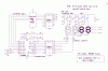
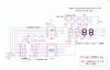
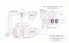
All the digits are connected segment A to A, G to G etc and the decimal points I have just added to one of the digits in a clock style, which is as the drawing. Jose only inverts the minutes to get the colon like clocks have, and the connections are seen as standard.
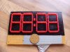
I once made another of Jose's clocks which was Charlieplexed and was a real wiring nightmare, I will post a picture of my clock display anyway, so you guys can see what you think of it.

Al
 
Hi Eric,

I have loads of 2N3906 which are 40v 200mA, they should be ok?

Al
hi,
Those 2N3906 will be fine.
Drawing almost complete, I have a 6digit CA LED clock a bit sometime ago on a BB, for a member.
I will program a 16F628A using that Hex file from Jumbo and modify the BB to suit. Better make sure there are no more bugs in the project before you build it.
Give me a couple of days.

I can send you a 74LS07 IC if you wish, PM your address.
 
Hi Eric,

Cheers mate the testing sounds good to me! Don't know what this forum would do without you!

I have taken a couple of pics of my display to see what everyone thinks.

Al
 

Attachments

  • MVC-472F.JPG
    MVC-472F.JPG
    74.5 KB · Views: 152
  • MVC-474F.JPG
    MVC-474F.JPG
    76.8 KB · Views: 156
hi Al,
Watch out for sunburn!

If your 16F628A is programmed with Jumbo hex, can you run the program, dont have the LED's connected and using a scope, see what if any signals you get on PORTA 1 and 0, pins 17 and 18.

I have no LED's connected yet on the BB, I see all the scanning pulses on all the pins except 17, 18, which appear to be set as inputs.

Tried 3 times to reprogram, lets now what you read on the scope.???

EDIT:
Tried a 16F628A from an older batch, that works fine, all scanning pulses present.

Will try the remainder of this new batch of 628'a later.
 
Last edited:
Hi Eric,

Strange that some PICs only work ok! I thought that the PICs were very reliable.

Glad you found the problem though as my mate borrowed my scope a few weeks ago and I don't think I will see it till after christmas, he lives in Bridlington and only calls every now and then.

BTW you need not stick to the 628, I have quite a few 16Fs and could swap over easy enough. If there is a better choice please let me know.

And as for sunburn! Not with these mate, they are very dull (well diffused) hehe

Thanks Al
 
Last edited:
hi Al,
I have it working with the original hex and with a change to the circuit.
You may have seen in the 'jose' notes than the minutes are upside, well they are literally upside down on the LED's !!, not just a drawing error.

Segment 'a' is at the bottom , 'd' at the top.!

As my LED's are on a block of four I cannot turn them the other way up, but you should be able to wire yours to suit.

Keep you posted.

EDIT:
Circuit diagram and expressch.sch file.
 

Attachments

  • Als_Clock1.sch
    20.9 KB · Views: 133
  • Als_ClockV1.gif
    Als_ClockV1.gif
    18.2 KB · Views: 162
Last edited:
Hi Eric,

That looks good but I thought you were planning for 2N3906s instead of the 07 as I have loads of them?

Is it any different with them? Yes I can easily change the segments around.

I didn't mean this to sound ungrateful but I have the trannies to hand and not the 07s

You have always been more than helpful to me, and other members of this forum I'm sure.

Also I need to drive each segment at about 20mA just so they are reasonably bright, they are as I said "well diffused", to the point of being a bit dim at levels much below 20mA, so the segment draw at an "8" would be 140mA and thats without the 1/4 duty cycle factor, so it may be the only way is to use transistors?

The LEDs are a batch that I bought very cheaply at a rally I think, some time ago and they are probably very inneficient, just tried one on my LED tester where I can put a superbright red LED on at about 2mA and it be very bright even then, these 5x2 reds are not even visible! Probably get heat burn before sunburn on these Eric hehehe

Thanks Al
 
Last edited:
hi Al,
The 2N3906's are for the Digit Anode Drive.

The 7407 are non inverting open collector high voltage/current outputs to drive the 2N3906's inputs.

As the LED anodes are at 12v/15V, the 7407 acts as a non inverting level shifters. I have some spare 7407 to post to you.

The ULN2803 is for the segment sinks, inverting.

Rather than rewrite the clock program I have modified the hardware to suit.

The BB 'lash up' of the clock I posted is 'ticking' away on the bench. I am getting quite good at reading the minutes upside down [ clock should be a winner in Australia]:rolleyes:

Eric.

EDIT:
You could do it this way if you have the bits on the shelf. Any TTT LS or CMOS inverter
 

Attachments

  • Als_Clock2.gif
    Als_Clock2.gif
    19.5 KB · Views: 159
Last edited:
Morning Eric,

Thats brilliant mate, I can now build it! I have loads of both 2803s and 40106s. :)

I might leave my segments upside down too, maybe we could start a trend, the australian minutes club. hehehe

Thanks for all the hard work mate, I really appreciate it and will post a working picture or two as soon as I get it going.

Thanks again, Al

hi Al,
To increase the Anode drive I have changed the resistors on the Bases of the 2N3906.

Can you figure out how to connect your inverters, if not just ask.
 

Attachments

  • AAesp05.gif
    AAesp05.gif
    19.7 KB · Views: 163
Last edited:
Hi Eric,

I was perusing the diagram and wondered if the 40106 inverts and then the 2803 inverts again, isn't the signal back to normal?

If so then why can't I connect the PICs outputs through resistors directly to the 3906 bases?

Just wondering thats all, please excuse my ignorance if I have missed the obvious as I seem to be having a blonde day today!

Think the reason for the blonde day is that my son, who is back home after a failed relationship, has just brought in a PAIR of fruit machines that he won on ebay for £23 and keeps wanting me to look inside them and fiddle about!

Strangely enough both of them work perfectly! Well I can't say he spent too much but boy do they take up some space!!!

Yours Al
 
Last edited:
Hi Eric,

I was perusing the diagram and wondered if the 40106 inverts and then the 2803 inverts again, isn't the signal back to normal?
Yes.
If so then why can't I connect the PICs outputs through resistors directly to the 3906 bases?
Because the 1k/4k7 are connected to +12V

Yours Al

Hi Al,

Lets know how it goes, use the segment resistor values to give the LED brightness you need, you Must a have segment resistor.
 
Hi Eric,

Right I see what you mean 12v, but what if I connected R1 between the base of the 3906 and 5v instead of tied to the 12v rail?

As I understood the transistor is a current device rather than relying on voltage like MOS/Fets, so wouldn't that still fulfill the requirement?

Please excuse all the questions mate but I learn more while talking on the forum than I ever do when reading stuff.

Thanks Al
 
LEDs are equally current devices
and when transistor is saturated, and starts pumping current into set of 4 leds forming the segment,
there is no limit for the current
you have used red leds
they generally drop 1.4V approx across each.
thus, total volatile drop would be 5.6V. balance of 12-5.6 would drive current
.
thus you need a current limiting resistor for each segment. hope i am able to express myself !!
 
Hi Sarma,

The LEDs I'm using are min1.8v max 2.4v so I chose 2v as a happy medium and as there are 5 in each segment thats 10v, so I'm only dropping 2v across the limit resistors, to keep the wastage down. I did try with 7 LEDs per segment and with a small resistor they did light, but sadly I the required 28 x 7 +4(for colon) =200 ! I was close though I had 192 of them. Good job I didn't have 200 though as when the segments were built and I tested them 3 were faulty.

Close shave eh!

Al
 
Hi Eric,

Right I see what you mean 12v, but what if I connected R1 between the base of the 3906 and 5v instead of tied to the 12v rail?

As I understood the transistor is a current device rather than relying on voltage like MOS/Fets, so wouldn't that still fulfill the requirement?

Please excuse all the questions mate but I learn more while talking on the forum than I ever do when reading stuff.

Thanks Al

hi,
The 2N3906 emitters are connected to 12V, so a 5V base voltage would not turn them OFF
 
Hi Eric,

Got it built but as usual I have teething problems! But at least no magic smoke, well actually not a lot of anything.

I noticed you have connected PIC pin 3 to GND and assumed that you have done this deliberately to cause the PIC to give the correct signals for the new configuration of the circuit, or you did it because you have CC displays, so I made the board so I can just swap a jumper to select either CA or CC.

I have checked all the circuit and the voltages are all correct on the correct pins, so I felt safe putting in all the ICs but alas as I said the circuit is dead.

I think I need to make a program to test the circuit while being simple. However I am confused with all the inverting and am struggling to decide whether to pull low or make high the PICs pins. What would be the absolute minimum program to see if the xtal is working ok,maybe light a single segment, any suggestions mate?

Anyway I am going back to checking paths and connections, just to recheck everything.

Thanks Al
 
Last edited:
hi Al,
PIC pin #3 is to 0V, for your CA LED's [ same as mine]

For quick check to see if the PIC is running do this,,, connect a 470R is series with a single LED [any colour] , connect the anode of the LED to 0V and while the PIC is powered touch the PORTA,0,1,2,3 pins in turn, with the free end of the 470R .

The LED should flicker showing that the Digits are being selected. [ best to disconnect your other IC's from PORTA while doing this part]

If that shows a LED flicker on PORTA 0,1 and 2 it shows the PIC is doing the digit select.

Now do the same for PORTB 0,1,2,3,4,5,6 , the segment drivers, these should also flicker the test LED when the end of the 470R is touched to each one, in turn.

Lets know what you get,:D


touch >> 470R >>>> LED >>>> 0V
 
Last edited:
Hi Eric,

Not a sausage I'm affraid! Think I need to look at the fuse setting or something.

Al
 
Update!

YES! It works now and showing 1202 as I type!

Thanks Eric and all you guys who helped.

Gratefully Al
 
Status
Not open for further replies.

New Articles From Microcontroller Tips

Back
Top