Continue to Site

Welcome to our site!

Electro Tech is an online community (with over 170,000 members) who enjoy talking about and building electronic circuits, projects and gadgets. To participate you need to register. Registration is free. Click here to register now.

  • Welcome to our site! Electro Tech is an online community (with over 170,000 members) who enjoy talking about and building electronic circuits, projects and gadgets. To participate you need to register. Registration is free. Click here to register now.

Quick question on 16F628A

Status
Not open for further replies.

bigal_scorpio

Active Member
Hi to all,

I have just built a jumbo LED clock from a design on Jose Pino's web page that uses a 16F628 and when I got to the stage of programming the PIC I found to my dismay that the packet I had it in was mislabled, the actual PIC is a 16F628"A".

All the research I did on the net seemed to point to the "A" being compatible with the code from a non"A". But on trying the code I am not getting much activity except the minutes digits showing capital "C"s but backwards.

I have tried various configurations of the fuses but that was the most I got. Is there a way of setting the configuration bits that would help me. I just wish I had a non "A" instead of the "A" version so I could rule out the differences.

Jose's page does not mention any special setting of the fuses and I have tried a good few combinations, but there are 7 fuses plus the protection one to choose and I doubt that the PICs legs will stand that many changes.

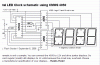
Here is a link to the clock pagehttp://www.josepino.com/circuits/led_clock

Any ideas guys........Al
 
Hi Al,
you may need to check the device migration document 40048a.pdf.

I'd give you a direct link, but Win7/IE9 seems to make me open the PDF directly with no URL.

Do a google search for '40048a.pdf' and it's the top result.

Regards.
 
"But on trying the code I am not getting much activity except the minutes digits showing capital "C"s but backwards."

shows code to help you, with port configuration or code
 
test each display, with a simple program such as displaying characters 0 through F.

do not try to do something difficult, without testing or simple basics.

see codes.
 

Attachments

  • segmentdecoder.asm
    11.4 KB · Views: 171
  • _7segasm.asm
    2.6 KB · Views: 190
What osc are you using? is MCLR a digital pin ? 0x3F50 works on both.. internal osc and all digital pins.

Hi Ian,

I'm using a 4Mh crystal and MCLR is not even connected, as far as I know all pins are digital.

Al
 
Hi Al,
you may need to check the device migration document 40048a.pdf.

I'd give you a direct link, but Win7/IE9 seems to make me open the PDF directly with no URL.

Do a google search for '40048a.pdf' and it's the top result.

Regards.

Hi Mickster,

I have read the migration doc, but found nothing that suggested it would not work.

As to Windows 7 try right clicking the link and then choose save as.

Al
 
test each display, with a simple program such as displaying characters 0 through F.

do not try to do something difficult, without testing or simple basics.

see codes.

Hi Fransisco,

Thanks for the test code, I will give them a try! Just wish I knew some ASM but it won't sink in I'm affraid. Too many years and pints I think. ;)

Al
 
May I suggest sending an email to Jose? He was kind enough to answer one of my emails a couple years ago. Be sure to ask what fuse settings he used (I'm not sure there are any fuse settings in that hex file).

Happy Holidays...

Mike
 
Last edited:
May I suggest sending an email to Jose? He was kind enough to answer one of my emails a couple years ago. Be sure to ask what fuse settings he used (I'm not sure there are any fuse settings in that hex file).

There are fuse settings in the HEX file, PUT is set, code protect is set, and osc is set to HS. The same value works on the 628A as well.

It's a pretty bizzare HEX file though?, rather strangely it includes all the blank addresses as well as the programmed ones (it doesn't use much of the 628's memory).
 
There is your problem.... If the chip is set to use HS instead of the recommended XT.. The XTAL caps may be giving you a problem... Running this in ISIS appears to work. So it must be to do with the osc setting.
 
hi Al,
The hex program runs OK in Oshonsoft for both 628 ans 628A.
Unzip this avi file to show the scanning.

Exactly which circuit have you built, I know its the Jumbo, but post the actual schematic from your link.

E
 

Attachments

  • als1.zip
    10.3 KB · Views: 172
May I suggest sending an email to Jose? He was kind enough to answer one of my emails a couple years ago. Be sure to ask what fuse settings he used (I'm not sure there are any fuse settings in that hex file).

Happy Holidays...

Mike

Hi Mike,

I was planning on emailing Jose but I wasn't sure what I needed to ask him. Looks like maybe something to do with the fuses or Osc settings.

Al
 
There are fuse settings in the HEX file, PUT is set, code protect is set, and osc is set to HS. The same value works on the 628A as well.

It's a pretty bizzare HEX file though?, rather strangely it includes all the blank addresses as well as the programmed ones (it doesn't use much of the 628's memory).

Hi Nigel,

Yes mate, I did look at the hex and from the bottom upwards it looks very strange! I wondered if it was corrupt until I got to the top.

Al
 
There is your problem.... If the chip is set to use HS instead of the recommended XT.. The XTAL caps may be giving you a problem... Running this in ISIS appears to work. So it must be to do with the osc setting.

Hi Ian,

I see what you mean but is there a solution?

Al
 
Hi Ian,

I see what you mean but is there a solution?

It makes VERY little difference, every example I've tried has worked perfectly regardless of the setting being XT or HS.

But you can simply set the fuse settings in your programmer before you blow the chip, HS for the oscillator, and PUT on, I wouldn't bother setting code protect on, it's a waste of time and effort.
 
hi Al,
The hex program runs OK in Oshonsoft for both 628 ans 628A.
Unzip this avi file to show the scanning.

Exactly which circuit have you built, I know its the Jumbo, but post the actual schematic from your link.

E

Hi Eric,

The scan seems to be ok mate. The schematic I used is the last one on the page, credited to Flash Gordon. I can't copy it mate!

My circuit is exact except that I am powering the 4050s from 12v instead of from the 5v rail. My segments are each 5x red 5 x 2 leds and at 25mm each look really good as they are diffused LEDs.

I have tested the segments and all are ok.

I have always wanted a large LED clock for my workshop and now my neck is getting worse I can't look up at my regular clock! So I thought I would finally get around to making one. I did attempt to start from scratch but my coding skills are definately not up to it and I just kept getting confused with the interrupts and timings (well most of it really) hehehe

Al
 
hi Al,
Look at this clip from the d/s for the 4050.

Are you using buffered 'B' or unbuffered 'UB' 4050's.?
 

Attachments

  • AAesp08.gif
    AAesp08.gif
    34.1 KB · Views: 222
hi Al,
As I suspected the 4050 when powered from 12V will not switch the output with a 0/5V input signal it..

The switching input must be at least +6V to be recognised as a logic high.

I suspect that Jumbo circuit is just another 'artists impression' !:rolleyes: Extract: This schematic is only a sample

To confirm the d/s, I have tried it using 4050's on a BB , it does not switch!
 

Attachments

  • AAesp05.gif
    AAesp05.gif
    14.6 KB · Views: 277
Last edited:
Status
Not open for further replies.

New Articles From Microcontroller Tips

Back
Top