Probe is fine. Just remember in x1 the input Z is 1M and in X10 it's 10 M.
3000 to 4000 seems like a weird frequency, Remember to take into account the possible doubling if you look at your FW ourput.
Do look at the power supply pins at each IC and at what stage it appears.
That first stage where the input Z is high, is suspecttable. Thus, it makes sense that it e a straight x1 gain amplifier that will amplify DC including the amplifier DC offsets.
 and see where can I filter things without jeopardizing the sensitivity.

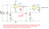
 ... Note cumulative losses across the diodes.
 .
.