Continue to Site

Welcome to our site!

Electro Tech is an online community (with over 170,000 members) who enjoy talking about and building electronic circuits, projects and gadgets. To participate you need to register. Registration is free. Click here to register now.

  • Welcome to our site! Electro Tech is an online community (with over 170,000 members) who enjoy talking about and building electronic circuits, projects and gadgets. To participate you need to register. Registration is free. Click here to register now.

Push On - Push Off latching Circuit using an NE555

Status
Not open for further replies.

dchero

New Member
Hello,

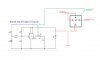
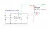
I made a flip-flop circuit using the NE555 to switch on or off some LED bars that I plan to put in my car.


Currently I have the LED bars hocked to a SPDT relay and they are setup to come on when the car dome lights come on (closing or opening the doors)

On port 87a on the relay I can either put a simple switch to turn them on when I want or put my flip flop circuit so I can use a spare button (DSC button from a mazda 3) to make it look like factory OEM.

Attached is the circuit schematic so you know what I'm talking about.


The problem is the following:

When I wan to turn the LED bars with the flop flop circuit it doesn't work as desired. They illuminate for a very brief second (fast flash) then go off.
What do I need to change on the circuit so that they turn on ?


Also, two videos.

Video number 1 shows the circuit working with an yellow LED on the board.

https://drive.google.com/open?id=1rYAsWHPrzEF-8H4ycrWxiZOjD1c6xuYZ


Video number 2 shows the problem.

https://drive.google.com/open?id=1Ok5R4Yos-i5ksmU7QHKmCk7PLgdjDi7Z


Thanks, looking forward to some help :)
 

Attachments

  • Circuit-Help1.jpg
    Circuit-Help1.jpg
    161.3 KB · Views: 259
The LTspice simulation below works fine.
Check all the connections and part's values on your circuit.

1582701350225.png
 
The LTspice simulation below works fine.
Check all the connections and part's values on your circuit.

View attachment 123365

Video number 2 doesn’t have the relay connected. Because the outcome is the same as the example in the video.

someone on another forum suggested to increase the cap size from 1 to 10 and remove the LED.

what do you think ?
 
someone on another forum suggested to increase the cap size from 1 to 10 and remove the LED.

what do you think ?
You could try those changes but I doubt that will affect the failure symptoms you are seeing.
 
It looks like the load current is simply too high for the 555 to run directly.

Try adding a transistor buffer to drive the relay or lights, rather than running them from the 555.
This is an example of a 555 driving a relay via a transistor buffer:

You should also really have a decent size capacitor across the power connections on any bit of electronics (eg. something like 100 - 470uF between 1 & 8 on the 555) and if you use a relay or inductive load, add a "flywheel diode" otherwise the inductive kick as it switches off can mess things up or damage components; that's D1 in the diagram above.

With a 555, the small cap from pin 5 to ground is also good practice.

Thank you for the help.
I changed the cap to a 10 and it works.

what value should the diode be ? As it is not mentioned in the diagram
 
Back with an update.

Attached is the updated circuit I used for the flip flop.

I changed the cap to a 10 μF, added a 0.01 μF from pin 5 to ground and a Diode to the signal output (N 4007).

It now works as it should but there is one problem i'm having.

When the relay switches off there is a small feedback that is beeing sent back to the flip flop circuit and for a fraction of a second the yellow LED on the board turns on and off.
Is there a way to eliminate this interference ?

I was thinking of adding a transistor BC 457, will that help ?

If so, can someone please help with it's positioning in the schematic ?


Thank you.


Here is the video showing the problem.

Video

Click 1 is a switch i use to turn on the relay (to simulate the car door opening). Click 2 is where I switch off the relay from the switch, that's when I get the small feedback in the flip flop.


Also attached is a picture of the Relay I am using.
 

Attachments

  • Circuit-Help-v2.jpg
    Circuit-Help-v2.jpg
    171.9 KB · Views: 250
  • Relay.jpg
    Relay.jpg
    461.1 KB · Views: 242
I changed the cap to a 10 and it works.
I don't see how the original value of capacitance was causing the momentary operation you were seeing, but I'm glad that it now works.
 
Final update

All sorted out.

The flywheel diode is in the correct position on the coil of the relay (pins 86 and 85) it's doing it's job :D


Thanks to all that helped !
 
Status
Not open for further replies.

Latest threads

New Articles From Microcontroller Tips

Back
Top