Continue to Site

Welcome to our site!

Electro Tech is an online community (with over 170,000 members) who enjoy talking about and building electronic circuits, projects and gadgets. To participate you need to register. Registration is free. Click here to register now.

  • Welcome to our site! Electro Tech is an online community (with over 170,000 members) who enjoy talking about and building electronic circuits, projects and gadgets. To participate you need to register. Registration is free. Click here to register now.

Proximity Circuit design

Status
Not open for further replies.

TimK

New Member
New to this forum and have a limited knowledge of electronics.

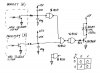
What I need is some help in the design of a circuit that will allow me to connect 2 identical proximity sensors (a) (b) in a way that when a metal object is detected by both sensor at the same time everything is OK. But if sensor (a) detects a metal object but sensor (b) does not I need to energize a relay.

The Proximity Sensors are 10-30V DC NPN Normally Open, 3 Wire, Switching Frequency 3kHz and are 4mm in diameter.

Relay would Have a 24V DC coil and a 5A contact rating. It will be used to light a warning Light and energize an air valve.

I am not sure how to do this and what I will need. I do know that the response time has to be quick. The metal objects will be traveling at about 800-1000 per minute and are less than 16th inch wide.

Any Ideas would be great

Thanks
 
Yes, If you need more Info let me know, I will see what I can find.


Type-Shielded
Operating Distance - 1mm
Differential Travel 10%
Repeat Accuracy 5%
Operating Voltage 10-30V dc
Ripple - 20%
No Load Supply Current - 10mA
Load Current 100mA
Leakage Current o.1mA
Voltage Drop 2.0V
Output Type NPN NO 3-wire
Switching Frequency 3kHz
Time Delay before availability 10ms
Input Voltage Transient Protection - Up to 30V DC
Input power Polarity Reversal Protection - Yes
Output Power Short Circuit Protection - Yes
Temperature Range - -25 to +75 C (-13 to 158 F)
Temperature Drift 10%
Protection Degree (DIN 40050) - IEC IP67
LED Indicators - Yellow (Output Engaged)
Housing Material - Stainless Steel
Sensing Face Material - Polyester
Tightening Torque - 0.8Nm
Weight - 26g
 
You can try something like this:

img_0003-jpg.33867


I used a CMOS 4011 NAND gate powered at 12Vdc but any NAND gate should work (using the right power supply, of course).
 

Attachments

  • IMG_0003.jpg
    IMG_0003.jpg
    37.7 KB · Views: 1,413
Or a little bit old school...a DTL NOR...assuming that the sensor outputs are low when metal is present.

Ken
 

Attachments

  • NOR-DTL.gif
    NOR-DTL.gif
    10.4 KB · Views: 634
Arkham00
This looks cool, Thanks very much.

I know that this is something simple for you but I am trying to understand how all this works. Could you give a brief explanation of what each component does in the circuit. I have a couple of questions about your solution.
1. It looks like the 2 resistors are 10K but what is the value of the resistor between the last gate and the transistor.
2. What is the value of the diode across the relay coil.
3. Are the capacitors 100p
4. I know the inputs of the un-used gate get connected to 0V dc but does the output get connected anywhere?
5. Where does the other led from the proximity sensor get connected? I am thinking to the +12V dc
 
You want to use a large slow industrial proximity metal detector to detect thousands of high-speed TINY little objects??? :eek:

The response time of that 3kHz detector is probably a few mS, maybe in the tens of mS. They are designed for high reliability, that means they are quite damped. And it probably requires a reasonble sized metal mass to trigger it.
 
Hi,

I agree with Mr RB. 3KHz is much too slow at a passage 800 to 1,000/min of 1.5mm size objects.

The MC33794 (Freescale) has an optimum sine wave frequency of 120KHz with low harmonics and uses an electric field to determine proximity. (up to 9 field sensors might be connected).

That of course requires an MCU for evaluation.

Your proximity sensor might be alright if used for car manufacturing to sense passing of a car door. :)

The problem would be easier to handle if those objects were magnetic using Hall sensors for detection.

Boncuk
 
Last edited:
Arkham00
This looks cool, Thanks very much.

I know that this is something simple for you but I am trying to understand how all this works. Could you give a brief explanation of what each component does in the circuit. I have a couple of questions about your solution.
1. It looks like the 2 resistors are 10K but what is the value of the resistor between the last gate and the transistor.
2. What is the value of the diode across the relay coil.
3. Are the capacitors 100p
4. I know the inputs of the un-used gate get connected to 0V dc but does the output get connected anywhere?
5. Where does the other led from the proximity sensor get connected? I am thinking to the +12V dc

Reply to your questions:
(1) 4700 ohm
(2) 1N4148 or 1N4002
(3) yes
(4) the output of the unused gate is floating (unconnected)
(5) yes, the power supply wire of the proxy is connected to +12Vdc

But pay attention to the other messages about the low speed of you proxy sensors. This is an important issue.
 
Hi TimK,

how about approaching the problem in a different way - optical?

There are reflective optical sensors with transistor output - CNY70.

They can be focussed within short distances and are - similar to remote control receivers - immune to light sources other than IR.

Attached are the CNY70 datasheet and an application note (Ant014).

If the resolution (speed) is not satisfactory refer to positioning and detecting sensors by Sharp semiconductor. They are sensitive in a range of 0.001 to 1mm.

You might try a complete reflective optical sensor kit offered by: ELV - Das Elektronik-Versandhaus | ELV Elektronik


Boncuk
 

Attachments

  • CNY70.pdf
    158.6 KB · Views: 284
  • CNY70-appli.pdf
    303.4 KB · Views: 279
Hi again,

the kit was offered 2003 and I doubt it is still available.

Here is the manual for the circuit including a schematic. Kick out what you don't need (e.g. the monoflop) and do some research with it.

Boncuk

P.S. If you need help translating feel free to PM me.
 

Attachments

  • 53799-MINI-LICHTSCHRANKE_KM.pdf
    200 KB · Views: 1,090
Last edited:
More Information

I really appreciate you help with this.

I have attached a drawing of what I am trying to accomplish. I may be on the wrong track completely. If anyone has a better Idea please tell me.

I am not concerned with complete accuracy in checking length. I just want to stop the process if the nails are about 1/8 inch short.

My concern in using a larger Proximity sensor is the distance between the nails. I think that with the larger sensor 2 or 3 nails would be detected at a time. So a short nail would not be detected. I could be wrong, I have been before.

Thanks
 

Attachments

  • Nail Checker.pdf
    22.8 KB · Views: 184
Also, I am not sure about optical solution. The enviroment is pretty dirty, (dusty and oily)

Thanks
 
I really appreciate you help with this.

I have attached a drawing of what I am trying to accomplish. I may be on the wrong track completely. If anyone has a better Idea please tell me.

I am not concerned with complete accuracy in checking length. I just want to stop the process if the nails are about 1/8 inch short.

My concern in using a larger Proximity sensor is the distance between the nails. I think that with the larger sensor 2 or 3 nails would be detected at a time. So a short nail would not be detected. I could be wrong, I have been before.

Thanks

A Detector built using a TDA0161, would probably be More Suitable.
 
Yeah that looks like an ideal app for one of the small automotive hall sensors. Most have a integral magnet, so they sense any ferrous metal passing by, they are used as "gear tooth sensors" for tachometer and fuelinjection sensing inside engines.

I know some FI engines use as many as 48 pulses per engine revolution, so they are good for about 48*5000rpm/60 = 4000Hz. Should be fast enough.
 
Mr RB, This sounds interesting, could you provide me with some instructions or a place to start. Like I said I new to this stuff. A quick google search reviled a large number of Automotive Hall sensors. Have you had experience any certain one that should work.

Thanks
 
Hi Tim,

using two TDA0161 connected to an MCU and comparing the resultant frequencies caused by the nail passage the sensors are independent of object (production) speed.

Sensor A senses every nail, even a missing one, while sensor B will sense the present and missing ones.

A completely missing nail will result in identical pulse patterns of sensor A and B and no action has to be taken. (misload)

Connect the MCU output to the switching circuit which stops production.

The function is illustrated in the sketch below.

Boncuk
 

Attachments

  • NAILS.gif
    NAILS.gif
    7.7 KB · Views: 258
Last edited:
Hi Boncuk,
What is your preference for a Micro Controller and do you know of a source for the sensors. I found data sheets on the web but no reference to anyone selling them.

Thanks
 
Hi Tim,

that design won't require a microcomputer. It more or less requires one XOR-gate to determine a short nail. It even ignores missing nails completely.
(mis load).

In the meanwhile I designed two cirucuits, one containing the sensor circuit around the TDA0161 with the option of horizontal and vertical mounting of the sensor coil.

The second board contains the power supply (selectable 115 or 230V) and the logic circuitry. The input uses a NAND Schmitt-Trigger for signal conditioning, being followed by the XOR-gate. The truth-table for XOR:

A-0, B-0, Q-0
A-1, B-0, Q-1
A-0, B-1, Q-1
A-1, B-1, Q-0

applied for the nails that means sensor A (top of nail) generates a logic 1. If the nail is long enough sensor B (bottom of nail) also generates a logic 1, leading to an output of logic 0. (Nail length within determined tolerance). If the passing nail is too short sensor B will generate a logic 0, causing the output to shift to logic 1. The following NAND gates are not necessary, but they must be connected anyway and are used as double inverter. The output controls T1 which energizes the self latching relay and putting out all three terminals (potential free) for further action.

If a nail is completely missing both sensors generate the same output (logic 0), meaning the (absent) nail is being ignored.

If the machine has been shut down due to a procuction failure the circuit must be completely disconnected from mains to reset it.

The sensor board is completely made with SMD components (except for three pin connector) for maxium freedom at the machine.

The PCB outline shows the cutting line if the sensor coil is mounted vertically, assuming a board thickness of 1.5mm and a coil height of 3mm.

The power and control board is single sided and contains two wire jumps + the jumps for mains power selection.

The circuit is designed for a gap of 2mm between nail and coil.

If you want to build the circuit as shown please PM me for the Eagle files.

Boncuk
 

Attachments

  • PROXIMITY-SENSOR-SCH.gif
    PROXIMITY-SENSOR-SCH.gif
    13.2 KB · Views: 382
  • PROXIMIT-SENSOR.gif
    PROXIMIT-SENSOR.gif
    18.3 KB · Views: 322
  • PROX-PWR-LOGIC-SCH.gif
    PROX-PWR-LOGIC-SCH.gif
    16.6 KB · Views: 261
  • PROX-PWR-LOGIC-BRD.gif
    PROX-PWR-LOGIC-BRD.gif
    22.8 KB · Views: 280
Last edited:
Status
Not open for further replies.

Latest threads

New Articles From Microcontroller Tips

Back
Top