Continue to Site

Welcome to our site!

Electro Tech is an online community (with over 170,000 members) who enjoy talking about and building electronic circuits, projects and gadgets. To participate you need to register. Registration is free. Click here to register now.

  • Welcome to our site! Electro Tech is an online community (with over 170,000 members) who enjoy talking about and building electronic circuits, projects and gadgets. To participate you need to register. Registration is free. Click here to register now.

problem with counter up and down circuit

Status
Not open for further replies.

klknight93

New Member
the problem of my circuit is jumping counts. I checked several times already . The stimulation is good . It will start as 0 and increase digit 1 by 1 . it has same result as down counter which is decreasing 1 by 1. However, it is totally different when coming to pcb board and breadboard. After i done the circuit, i tried at breadboard and found out there are few problems occurred . First, it will start with 999 after power supply is connected. Come to the counter up and down , it will keep jumping . I tried switch debouncer too and it is the same result. Currently , i am still check the problem and found out Q0 from 74ls192 will keep on no matter button for up or down. Below there shows the general design and detailed image for connections from proteus . This design on pcb already cost me for 2 weeks and still cant get the solution.


upload_2017-12-30_12-49-54.png


upload_2017-12-30_12-51-7.png
 

Attachments

  • upload_2017-12-30_12-45-3.png
    upload_2017-12-30_12-45-3.png
    173.2 KB · Views: 215
Hi KLK

Welcome to ETO .. .. .. ..

I am a long way from being any kind of expert, however I do recognise that circuit as very similar to one I built a while ago. I think your problem may be the 'floating' pins on U1, U2 & U3 .. .. .. .. I think D0 - D3 on each chip should be grounded.

If I'm wrong, someone with a better understanding will leap in and correct me, for sure ..

S

 
If you're not using the parallel load then I don't think the value on D0-D3 matters. However, it is good practice to ground unused inputs.

I suspect your problem is with contact bounce. I've never seen a switch arrangement where the button discharges a capacitor. Try changing to a more conventional debounce circuit.

Mike.
 
Old fashioned TTL ICs needed a supply bypass capacitor at each IC.
Your new circuit has its diodes connected to numbers instead of some circuitry. There is no debouncing.
 
All this can be done with one microcontroller and you can add debounce and all sorts of other things without having to add a single new component.
I have not used chips for 20 years. They are all in the rubbish bin.
 
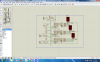
Having a switch discharge directly a debouncing capacitor is common. You could stick with it, but the circuit has other problems.

Yes, ground the unused data inputs. Even though they are not used internally, they still have active input stages that do *not* like to float.

Bounce: In the original circuit, the debounce R and C are too small. The debounce period is only about 700 microseconds. Increasing both the R and C values should fix this. BUT -

These counters act on a positive edge, which is the trailing (slow) edge of your inputs. You need to reverse the input components so there is a positive edge when the button is pressed, not when it is released. BUT - you are using TTL chips, which require a fairly low impedance path to GND to be seen as a logic low. Try this:

Connect the switch between the count input and Vcc. Connect both the resistor and capacitor to GND. The switch now will make a rapid rising edge to the count input, what it wants to see, and the capacitor will filter out the bounce. The resistor must be small, like 1K for LSTTL and 470 ohms for standard TTL (330 preferred). And the transition level is around 1.8 V, significantly below Vcc/2. These combine to make the debounce capacitor much larger. Start with R=1K and C=100uF for a debounce period of around 50 milliseconds.

This also will have the capacitors hold the count inputs low during power-up, which will help with the 999 problem.

999: The counter increments on a positive-going edge. When power is applied, R5 and R6 apply count edges to both the up and down inputs *after* the power-on reset input has ended. It looks like the down count is coming in last. Increase C3 to 10 uF and increase R1 to 100 K.

I think the real solution to the 999 problem is reversing the input logic polarity explained above. If everything works, try decreasing C3 to 1 uF and then 100 nF and see if everything still works.

ak
 
Last edited:
Colin, your response does nothing to help the OP learn about his circuit.
All this can be done with one microcontroller and you can add debounce and all sorts of other things without having to add a single new component.
After only a few *months* of learning how to deal with a PIC, the biggest PITA in the uC world. I assume you are going to pay for the OP's PIC development kit...
I have not used chips for 20 years.
That explains sooooooooooooooooo much.

ak
 
Hi AK, and Thanks .. .. .. .

Not my thread, but I was interested to learn from the solution to the problem.

The only issue I could see was the floating inputs but I wasn't sure whether that was an issue or not. Your outline however, makes a lot more sense to me .. .. .

I should apologise for my sarcasm to Colin .. .. .

Thanks again

S
 
I should apologise for my sarcasm to Colin .. .. .
Steady on there Mr Music old chap!
Don't go getting all huggy and fluffy on us.
Colin is a big boy, I am sure that he can take it, as well as give it out!

HNY to all.

JimB
 
I should apologise for my sarcasm to Colin
Don't. His record of unhelpful "advice" is legend on this and other fora. In my first month after joining here, his response to three different people in three different threads basically was you're too stupid to understand my answer, come back in 20 years after you've learned something, get out of electronics before you kill someone, everything you're doing is wrong - use PIC, etc. I used to tiptoe around him until I read the way more experienced members (including a moderator) respond to him. He's not stupid nor inexperienced, but in my direct experience the odds of him giving useful advice appropriate for the experience level of the OP is around 5%. Colin thinks I'm an idiot, but he thinks everyone is an idiot. That actually is a clue.

ak
 
Steady on there Mr Music old chap!
Don't go getting all huggy and fluffy on us.
Colin is a big boy, I am sure that he can take it, as well as give it out!

HNY to all.

JimB
Agreed! Interesting that combinational logic, counters and shift registers are still lessons on his site.

Anyhow!!! Lets not fail the OP and get back on topic...
 
Anyhow!!! Lets not fail the OP and get back on topic...

Yes, absolutely .. ..
I'm sorry, I didn't mean to hijack the thread .. .. .. .
I'm quite sure the help the OP needs is available to him now, Thanks to AK .. .. .. .

S
 
i i i e ?

LOL .. No, nothing so complicated.
Just an old habit of mine related to the writing of too many school reports and a dysfunctional OCR system !

.. .. .. . and whilst I'm writing ..

HAPPY NEW YEAR EVERYONE :)

s
 
guys , i tried to use my circuit just shown above , now left bit more then success , i will post a complete circuit after i done . thanks for giving such many info and i really try them .
 
guys , i tried to use my circuit just shown above , now left bit more then success , i will post a complete circuit after i done . thanks for giving such many info and i really try them .
Does that mean it worked?

Mike.
 
yesterday it worked( by using and gate, my counters can be increased 1 by 1 from 0 to 9 but another function cant , u just can succeed either up or down) , but now it is spoiled again T_T . no idea which part making wrong again .
 
Status
Not open for further replies.

Latest threads

New Articles From Microcontroller Tips

Back
Top