mikaelmark
New Member
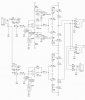
I´m testing several discrete OpAmp´s for my DIY portable headphone amplifier (with first generation NiMh 16VDC/2Ah battery pack), all with good results. And the batteries are drained to about 7VDC, then the volume will be a lot lower and if going below the OpAmp´s working voltage, it will also be distorted. Now, I wonder about some things (please see attached schematics):
1. As the input power is directly connected to the +/-15VDC output at the voltage regulators LM317/LM337 to minimize the power draining from the battery, so also the voltage reg´s and the two big power power filter cap´s and of course also the rectifier diodes, will not be used - may the voltage reg´s draw any mAh current backwards, altough there are no draining component at this direction other than the unused power stage. Maybe it´s best to remove the whole power section (by removing the voltage reg´s or cut the PCB´s copper conductor´s for the output pin´s)?
2. Should the two big filter cap´s (with original value 4700uF swapped to 10000uF) be used altough the amp is running by batteries, or will the OpAmp be satisfied without them powered in realtime directly from the batteries?
3. Can I safely remove all the three (or any of them) LED´s for the amp, to minimize the battery draining?
4. As those discrete OpAmp´s will accept 24VDC, will it be fine if raising the batteries voltage to something between 18 and 24VDC?
5. With above in mind, should the amp be better if replacing the NiMh with Lithium, such as dynamic and transient speed etc?