i would like to know how this circuit works ?? please help me .
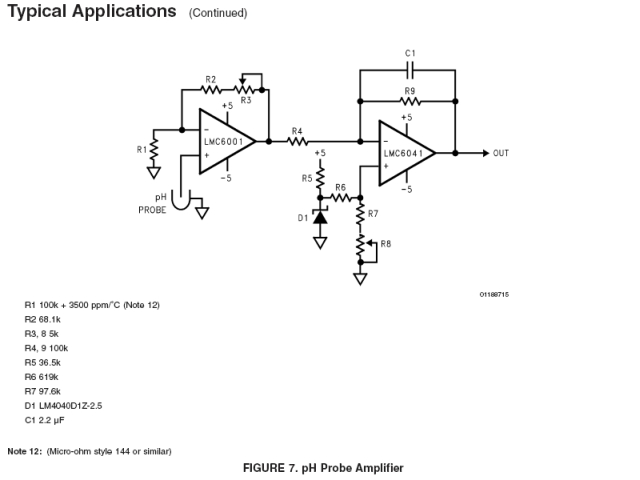
i want to know wheter we have to use a PTC thermistor or NTC thermistor as the variable R1 resistor .and also i cant understand how the second section of the ph meter works?? can any one help me?
as far as i understood the second stage is a differential amplifier with non inverting input of .35 volts. but shouldnt it be .700v ??? so as to display PH in the range of 0-1400mv?? (0-14 PH ) .
thank you
Last edited:
")