Continue to Site

Welcome to our site!

Electro Tech is an online community (with over 170,000 members) who enjoy talking about and building electronic circuits, projects and gadgets. To participate you need to register. Registration is free. Click here to register now.

  • Welcome to our site! Electro Tech is an online community (with over 170,000 members) who enjoy talking about and building electronic circuits, projects and gadgets. To participate you need to register. Registration is free. Click here to register now.

Need help with this circuit.

Status
Not open for further replies.

gary350

Well-Known Member
This 555 siren circuit came from the TTL book I built it output is probably 1/2 watt. I want it louder so I added a mosfet. I think the speaker needs current limiting resistor R1. I'm not sure how many amps 3 lithium batteries in series are. .5 amp at the speaker will be .5 x 12 = 6 watts. 12v / .5 = 24 ohms for R1 is that correct?
100_7614.JPG
 
The output of the 55 timer is a totem-pole. There is a transistor that pulls the output up to Vcc and another one that pulls it down to ground (by which I mean battery negative). The amplifier stage you added only switches to ground and so there is not really a path to +12V when the 555 output is low (to remove the energy from the speaker coil).

The easiest fix is to add a comp;lementary (P channel) MOSFET to pull the circuit output to +12V when the 555 output is low. The P channel source goes to +12V, the gate goes to 555 pin 3, same as the N channel gate, and the two drains are connected together and to one side of the speaker. Connect the opposite side of the speaker to ground (or +12V) through a capacitor so the speaker can see both polarities.
 
The easiest fix is to add a comp;lementary (P channel) MOSFET to pull the circuit output to +12V when the 555 output is low.


As the 555 output transitions from one state to another, there will be a time period when both FETs are on at the same time. This is called cross-conduction, or shoot-through, and can cause serious overheating in the devices.. The bipolar 555's internal output stage is famous for having this problem, but the current spikes in the circuit you suggest will be much worse.

ak
 
What is the power rating of the speaker?

ak

I will have to look at my collection of speakers. I have several 3W. It has been 12 years sense I looked at the speakers I think there are several higher watt speakers. I recall several 10" diameter speakers.

This is the original circuit.
100_7616.JPG
 
The output of the 55 timer is a totem-pole. There is a transistor that pulls the output up to Vcc and another one that pulls it down to ground (by which I mean battery negative). The amplifier stage you added only switches to ground and so there is not really a path to +12V when the 555 output is low (to remove the energy from the speaker coil).

The easiest fix is to add a comp;lementary (P channel) MOSFET to pull the circuit output to +12V when the 555 output is low. The P channel source goes to +12V, the gate goes to 555 pin 3, same as the N channel gate, and the two drains are connected together and to one side of the speaker. Connect the opposite side of the speaker to ground (or +12V) through a capacitor so the speaker can see both polarities.

#2 circuit I found online, it is P channel mosfet like you mention. The 555 drives the transistor and the transistor drives the mosfet.

I have no clue if any of these circuits work. I can build them but I can't design them.

100_7645.JPG
 
For a fixed supply a bridge circuit will increase output (by a 4X factor) :


You could use an h-bridge to drive it. Like L298N


Regards, Dana.

That would be great if I had a circuit drawing to build it from.

Google search says L298N is a motor control circuit.


Google search for 10 Watt Audio amplifier I find a 20W audio amp for $3

 
Last edited:
1684674591222.png


Basically you connect the speaker between out1 and out2, and add diodes as shown

1684674909731.png
Ignore motor shown, thats your speaker. The Batt is your power supply.

Next you add the Rs to limit current thru speaker, start with 100 ohms
before you lower it to raise current. You need to know what the speaker can
handle.

Next you need to supply 5V for the logic supply pin and the enable pin.

Last the two control inputs come from 555 timer, to IN1 and In2, one must be inverted.
These are 5V signals. You can use single gate logic to do that or use a simple transistor
inverter on one of them. Or use the other bridge in part to do the inversion. Or use your
circuit with the 2N3904 inverter to do it.

You can also do this with a audio amp :

1614773702147-png.167834

The above is one chip.


Regards, Dana.
 

Attachments

  • 1684674068617.png
    1684674068617.png
    63.6 KB · Views: 208
Last edited:
That would be great if I had a circuit drawing to build it from.

Google search says L298N is a motor control circuit.

A speaker is essentially a motor - both convert electrical energy to mechanical movement - for your crude and nasty application (square wave to a speaker) it would be perfectly fine.
 
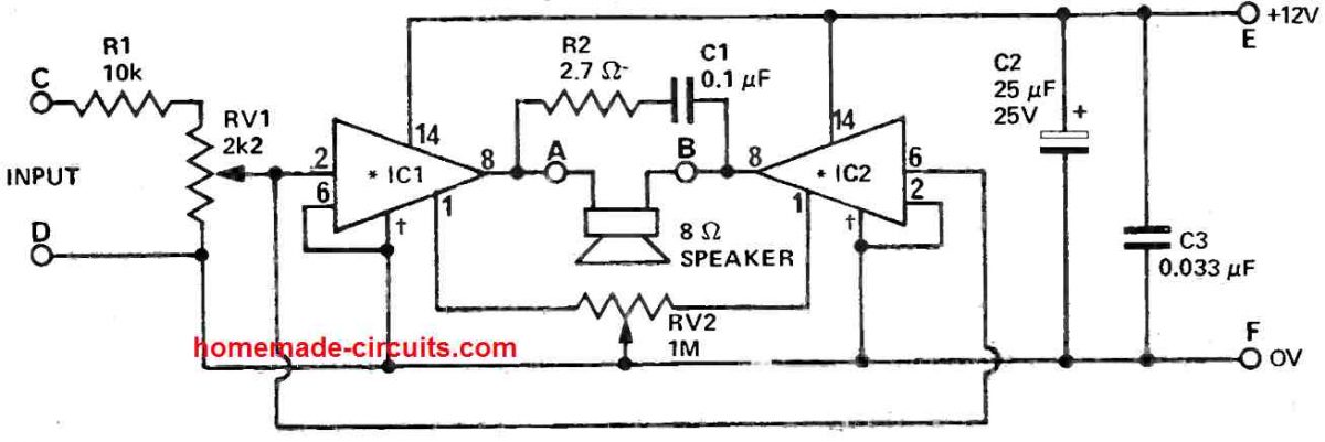
an LM380s can produce more output current than an LM386 then two LM380s produce much higher output power when bridged into an 8 ohm speaker.
But two LM386s when bridged into an 8 ohm speaker produce almost the same output power as one LM386 but produce much higher heating.
 
But two LM386s when bridged into an 8 ohm speaker produce almost the same output power as one LM386 but produce much higher heating.

audioguru why is that the case ?


Regards, Dana.
 
The LM386 has an approximate output impedance of 6 Ohms so when bridged with twice the voltage doubles the current into 8 ohms or in other words now has a 12 ohm source to an 8 ohm load.

Although the output stages look similar, but are not the same.
Heatsinks will reduce temperature rise in both cases.
 
The LM386 has an approximate output impedance of 6 Ohms so when bridged with twice the voltage doubles the current into 8 ohms or in other words now has a 12 ohm source to an 8 ohm load.

Sorry, but that's utter nonsense - the LM386 as with any 'normal' semiconductor amplifier has a VERY low output impedance, probably 0.1 ohm or less?, it's not a figure which is really of any use, so is rarely (if ever) given.

If an amplifier had an output impedance of 6 ohms it would be utterly useless.

When you bridge two amplifiers, each effectively sees half of the load impedance, so the 4 ohm capable LM386 when bridged needs a minimum load of 8 ohms (giving 4 ohms to each chip).

As for AG's confusing post, I suspect there was a typo - and he meant to say LM380 and not LM386 as producing the same power.

But the OP doesn't need an audio amplifier, as he's not using 'audio', simple switching is all that's needed.
Your comment shows you do not know how to read datasheet plots .

The 1st principle of finding output impedance to measure the load that produces 50% of the no load voltage. OR power. We can see this in the plots of 4, 8, 16 ohms where the 50% drop in output occurs. That is the load regulation or its inverse output impedance..

The 2nd is the Theorem of Maximum Power Transfer, (MPT) where the matched load impedance is 50% efficient or 50% of the supplied AC power to power the load. ( just like 50 ohm matched Z in RF systems)

The LM386 has a closed loop gain of10 with reduces the higher output impedance of the low quiescent current by a factor of 10 and also has the benefit of low idle current. The Rbe or re is a function of bias current. which was designed to be low to minimize battery power idle current.

You must be thinking of a 100 W amplified or output stages with high idle current. and not these IC's rated for about 0.7W and 2.5W . Perhaps AG will analyze it his way to backup his correct analysis.

Please do not criticize me without evidence and theory as my wisdom has accumulated for 50 yrs now, although brain-farts are more likely now.


I respect your repair experience, but your insulting remarks are just ignorant. If you cannot read the plots, I will show after your apology and also the same applies to AG's skill and experience.
 
Last edited:
1684758702424.png
LM386
 
All (unless there are -R elements or other mathematical oddities in the HW)
one and two pole amplifiers, have finite Zout, and that Zout rises as
the amp runs out of G at higher freq. One can do the LaPlace analysis
and using PFE can determine it looks inductive and what the values
comprising Zout are at freq. Lots of fun actually doing this.

Tony, welcome to my club, or yours me -
although brain-farts are more likely now.


Regards, Dana.
 
Last edited:
Hey , sorry to offend you Nigel.
 
Hey gary350 ,

Here's my best advise, as Nigel said, you only need a switch. Since you have an NPN use that with a similar current rating diode and Rb = 10 to 20 x the speaker impedance. This will use the low inductance of the speaker air coil in a magnet as a flyback to continue the current with a square wave voltage and exponential current.

My advice is only use two LIPO batteries to get 4 to 6W of power or reduce with a higher Rb.
I simulated 2 to 3 cells here with a slider so you can see the power output which is high (95%) efficiency since it is operating in Class D mode. (?) or switched mode.

https://tinyurl.com/2pq4os43 < Falstad sim

1684764912964.png


The NPN only draws <<0.3 W avg and a 1N400x will work.
 
Last edited:
there will be a time period when both FETs are on at the same time. This is called cross-conduction,
Certainly true but I really doubt it will matter much in this application. Especially with relatively high RDSon transistors.

But I like the flyback diode solution proposed by Tony
 
Status
Not open for further replies.

Latest threads

New Articles From Microcontroller Tips

Back
Top