Continue to Site

Welcome to our site!

Electro Tech is an online community (with over 170,000 members) who enjoy talking about and building electronic circuits, projects and gadgets. To participate you need to register. Registration is free. Click here to register now.

  • Welcome to our site! Electro Tech is an online community (with over 170,000 members) who enjoy talking about and building electronic circuits, projects and gadgets. To participate you need to register. Registration is free. Click here to register now.

Peak meter for certain frecuencies

Status
Not open for further replies.

Menticol

Active Member
Hello

I'm building my own home audio system, and I would appreciate some help.
I want to make a peak meter, based on the circuit shown on this page (Thank you jrz126)

https://www.electro-tech-online.com/threads/lm3915-help.13142/

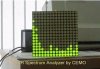
But I wanna make a bar for each octave, for example 60, 80, 120, 240, 1K, 3K, 8K, 15K, etc. like the professional analyzers. I think mayble putting a high-pass or lo-pass filter on the entrance of each LM3915 I could do the job. But I don't know what value of condensers / coils to use. Or am I totally wrong?

Thank you very much, in advance!!!
 
You will need individual bandpass filters for each of the frequencies stated. I think Microchip Technologies has a freeware filter designer that would let you figure what you need. A bandpass filter is a combination of high- and low pass filters, by the way.
 
audio spectrum analyzer

Here is most of what you need. There are 10 filters and one meter doing the job of 10. The circuit switches the one meter over the 10 filters faster than the eye can see so it looks like there are 10 meters. resolution of 10 x 10.
32Hz, 64Hz, 125Hz, 250Hz, 500Hz, 1kHz, 2kHz, 4kHz, 8kHz & 16kHz.
I found this at Eagle CAD Software web sight under downloads—audio.
 

Attachments

  • Audio Spectrum Analyzer(En).pdf
    457.1 KB · Views: 2,288
That is a nice audio real time analyser circuit.
It should use an LM3915 that has -3dB logarithmic levels because our hearing's response to loudness is logarithmic. The LM3914 in the circuit is not logarithmic, it is linear with reduced range.

Loud music levels will be crammed together and lower levels will be separated too much with an LM3914.
 
Wow

ronsimpson said:
Here is most of what you need. There are 10 filters and one meter doing the job of 10. The circuit switches the one meter over the 10 filters faster than the eye can see so it looks like there are 10 meters. resolution of 10 x 10.
32Hz, 64Hz, 125Hz, 250Hz, 500Hz, 1kHz, 2kHz, 4kHz, 8kHz & 16kHz.
I found this at Eagle CAD Software web sight under downloads—audio.
You have provided a wonderful schematics and knowledg by PDF
Thanks BUDY;)
 
Menticol said:
I'm sorry by the delay, thank you so much ronsimpson! Im looking foward to build the project, but I'm a bit afraid because it seems a little expensive.

That's because it is expensive, it's a very complicated circuit because of the large amount of duplication.

Anything remotely modern would use a DSP or microcontroller, simplifying the hardware at the expense of complicated software - using FFT (Fast Fourier Transform).
 
The circuit designer got a couple of things wrong in his discussion of the circuit:
 

Attachments

  • bandpass filter.PNG
    bandpass filter.PNG
    17.6 KB · Views: 331
Pins 4 and 7 should also be connected to a power supply.
 
Menticol,

If you build this project……
Audioguru is right, use the LM3915 not the 3914.
Audioguru and Hero999 mentioned the power supply pins in the opamps need fixing.
You should go to Eagle Cad and download their free software. Make the corrections to the schematic and PCB files. Then have PCBs made. If you need help with the CAD software I could help you.
 
The main schematic uses quad opamps and their pins are correct.

The discussion of the circuits had the pins on the opamps wrong.
 
Thank you again, Ronsimpson. I'm trying to put the schematics on the EagleCad, but I'm still too novice with the program and any (very probable) mistake is a money waste. I would prefer to make the changes between the printed circuit and the socket of the IC using wires and some epoxic. I know it is not very professional but I hope it works.

Please, What does 2n2 mean in the capacitor's value?
Example: 1u = I assume 1 Uf
22n = 22nf
But 2n2? I have seen the same thing on resistors value, number, letter (example K) and another number (instead of omega)

By the way. do you know about any other mistake on the circuit, Audioguru?

In advance, thank you all of you for your help, I will keep posting about the progress of the project and I hope my progress, pictures, conclusions, etc could be useful on any way to all of you
 
Last edited:
I think the pcb is correct but I didn't look long. The theory discussion is wrong. I am a poet because I rhyme all the time!

2n2 is 2.2nF, 1k5 is 1.5k ohms. They replaced the decimal point with the "n" or "k". I have some 470pF capacitors that are marked n47 (0.47nF).

Here is another audio spectrum analyser project. It uses a microcontroller to make the hardware very simple:
https://www.electronics-lab.com/blog/?cat=8
 

Attachments

  • spectrum analyser.JPG
    spectrum analyser.JPG
    14.7 KB · Views: 249
It looks great, but I have no idea about microcontrollers nor this screen :(

Back with the first poject, how many volts does this thing consume? I can see 3 pins for power, but no idea about the other two, and I can't see anything on the pdf
 
I didn't spend much time trying to see what connects to what.
It looks like the LM3915 sinks 12.5mA through the horizontal rows of LEDs. That is not enough current because the multiplexing reduces the duty-cycle and brightness of each LED to only 10% which is only 1.25mA. Very dim.

The project is confusing because it uses many connectors but the details about them are written in Vietnamese.

The current-limiting for the LEDs is done inside the LM3915. So when a 12V supply is used and all LEDs are turned on then the outputs of the LM3915 are 8.5V (3.5v blue LEDs) with 12.5mA. Then all ten outputs dissipate 1.1W. If the LEDs are 1.8V red ones then the LM3915 dissipates 1.3W. Its absolute max allowed dissipation is 1.365W.
If a 9V supply is used then the dissipation in the LM3915 with blue LEDs is 0.69W and with red LEDs is 0.9W which is better.

The opamps and Cmos logic ICs work fine with a 9V supply so I would power the project with regulated positive and negative 9V supplies.
 
The multiplexing may need improving?

the Oriental circuit that Ronsimpson posted is the revised circuit I may end up building but Audioguru thinks the display needs work?
I WAS going to build a very similar circuit based on the Vellmsan eq circuit and the Oreintal circuit but noise in the display would prevent using so my plan now is to build the oriental circuit and a TILT circuit, connect in parrell .
the low current that audio guru points out would be the max current draw if ALL the leds are on at once.
need to redesign the multiplexing circuit?
thought about adding transistors to the lm3916 outputs?
considering using quad bi lateral switches?
lots of options. Even thinking about a constant current sensor type circuit??
just food for thought
 
oh and the fft circuit==too old(me), can't afford to invest in programming hardware. looks easy enought BUT
 
The number of LEDs lighted has nothing to do with their current. Without transistors driving the LM3916 ends of the rows then the multiplexing will make the LEDs look too dim.

All the LEDs are never turned on at the same time. Just a sinlge column when its signal level is very high.

It would take a lot of parts to make 10 constant current circuits. Use resistors instead.
 
Status
Not open for further replies.

New Articles From Microcontroller Tips

Back
Top