Continue to Site

Welcome to our site!

Electro Tech is an online community (with over 170,000 members) who enjoy talking about and building electronic circuits, projects and gadgets. To participate you need to register. Registration is free. Click here to register now.

  • Welcome to our site! Electro Tech is an online community (with over 170,000 members) who enjoy talking about and building electronic circuits, projects and gadgets. To participate you need to register. Registration is free. Click here to register now.

parrot sounding ac doorbell

Status
Not open for further replies.

desperadogear

New Member
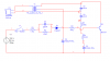
i have seen this circuit in an electronics magazine. this is a doorbell circuit that is supposed to produce parrot like sweet sound without requiring any musical ic.I have attached the circuit diagram. there is a small change that instead of buzzer, the primary of transformer is given to a loudspeaker of .5 W 8ohms. WIll this circuit work??

I doubt because I have tried simulating it in multisim but im getting very weak output at the buzzer (some nV) .. please check this and reply the changes required in order that this works
 

Attachments

  • acdoorbell.png
    acdoorbell.png
    13.8 KB · Views: 1,213
Last edited:
Don't double post.

I don't know, it looks like some kind of oscillator, I can't tell whether it's a colpits or hartly configureation, it might be a combination of the two. T1 is tapped and therefor provides feedback to the base of Q1, there again C4 and C5 form a tapped capacitor which as well as forming a tuned circuit with T1 is connected to the base of Q1 via T1.
 
The supply voltage is really 230 VAC??? Wouldn't there be a lot smoke, maybe some flames? Don't think I'd want to push that button on a rainy day...

Anyway, figured the high voltage supply might be a problem for your simulation. Not sure why there is a buzzer and not a speaker, but then again... Parrots mostly make loud squacking sounds (none too sweet).
 
I wouldn't work without 1k across it since the doide rectifies the AC, the capacitor would just charge up, then nothing would happen, the resistor allows it to discharge on negitive cycles.
 
If you want a parrot sounding door alarm, try one of these!
No need for AC, just a few seeds.

JimB
 

Attachments

  • Percy.JPG
    Percy.JPG
    80.8 KB · Views: 506
Hero999 said:
I wouldn't work without 1k across it since the doide rectifies the AC, the capacitor would just charge up, then nothing would happen, the resistor allows it to discharge on negitive cycles.

Yes, you need a resistor across it (basically to discharge it when you turn the power off) - but no where near that low!, do the ohms law and work out the current through the 1K!.

A capacitive dropper is a common technique, if you need low power, small size, low cost - and don't mind that the entire circuit is live!.
 
description given in the magazine

HarveyH42 said:
The supply voltage is really 230 VAC??? Wouldn't there be a lot smoke, maybe some flames? Don't think I'd want to push that button on a rainy day...

here is the description given in the magazine.. The oscillation frequency depends on the combination of resitors R4 and R5 and capacitors C3 , C4 , C5 . when the switch is closed the audio signal generated due to oscillations is amplified by transistor bc337 and parrot like sound :) is reproduced from loudspeaker connected across the secondary of transformer.
Audio transformer used is to transform the high impedance of the output amplifier to match the much lower impedance of the speaker. The audio transformer is normally used in transistor radio. If a wrong transformer is used, the result can be low output.
The audio frequency across the speaker terminal is about 3 khz.the operating dc obtained at cathode of diode D1 is about 6v. However if you press switch s1 continuosly for a few seconds the maximum voltage develped at this point may go up to 20v which must be avoided to prolong the life of the circuit. R1 limits the surge current and capacitor limits the circuit current to a safe level for circuit operation. R2 across C1 provides DC path for current aswell as a discharge path when the circuit is switched off. This is to prevent a possible shock to the operator by charged capacitor C1
 
desperadogear said:
R2 across C1 provides DC path for current aswell as a discharge path when the circuit is switched off. This is to prevent a possible shock to the operator by charged capacitor C1

But it CAN'T be 1K, that's FAR too low, and as suggested as soon as yopu pressed the button the circuit would disappear in a cloud of smoke (and possibly flames?).
 
Using the average doorbell push switch to switch 240v is verging on criminally negligent.
At least with any of the cheap doorbell switches I have seen.

What magazine was stupid enough to publish this rubbish?

In the circuit as simulated, the buzzer should be a loudspeaker (as mentioned elsewhere), there is a big difference.

JimB
 
I haven't used Multisim in a while (didn't fit my needs), but pretty sure there was a loadspeaker model. The supply voltage can't be 230 VAC mains, use DC. Here in America, I believe doorbells are commonly 24 Vdc (never had one myself).
I don't think the magazine published the circuit as shown, you should go back and recheck everything. You probably left some component values at Multisim default, instead of the required values.

Can you post the magazine title/issue information? I'm guessing that posting a scan of the article wouldn't be too legal.

My interest in this, is that my neighbor has a macaw, which squacks all the time (probably his cats messing with it). Figured I'd make a sound activated version...
 
i have checked the components of the circuit again , its the same except that there is a loud speaker in place of the buzzer.. The magazine in which the circuit was published is ELECTRONICS FOR U, india (june 2006, vol. 38, no.6, pg. 87)...
here in india the mains supply is 230v ac. The magazine claims to have tested this circuit .. wonder if the person who tested this is still alive. . Anyhow i have decided not to take risk as my house is filled with wooden furniture.. lol.. thanks to everyone and sorry for the trouble..
 
Oh no, another house with wooden furniture, concrete, glass and stainless steel are not apealing much these days.
Just kidding ;-)

although current is low (~ 0.1A), and duty cycle is only 50% (only positive halfperiod of the sine),
and the use is short (unless you find someone to like the sound keep the doorbell knob pressed for an hour),
voltage drop is quite significant and you would need both R1 and R2 to be some 10W resistors.
Is this mentioned in the article?
 
Last edited:
Nigel Goodwin said:
Yes, you need a resistor across it (basically to discharge it when you turn the power off) - but no where near that low!, do the ohms law and work out the current through the 1K!.

I agree, that was a pretty stupid thing to say and that capacitor won't have much effect with 1k across is.

Nigel Goodwin said:
A capacitive dropper is a common technique, if you need low power, small size, low cost - and don't mind that the entire circuit is live!.
Yes and a bridge recitifier with zenner and smoother capcictor on the output is the normal way of doing this.
 
I went to the magazine website, but apparently you have to pay to access the circuits (yeah its listed). You can register, and get access to some circuits and stuff, just not the most recent (or maybe the websit is buggy). Didn't mess around much there.

None of the components in the circuit appear to be consistant with a high power supply (220 in America is used mostly for large appliances). I know very little about 220 mains, except a couple of unfortunate and very unpleasant experiences (are you people nuts or what, the whole house 220 3-phase).

Anyway, try using a 9 volt battery instead of the mains. Hook ip the osciloscope in multisim and see if there is oscillation. Speakers and audio don't simulate well, unless you have a very fast computer.

I did find a Canary Doorbell circuit, had a wav file on the site, sounded pretty cool, might be able to swap a few parts to change the frequency.
 
This circuit says unknown author, so figure its fair game. I was going to post the WAV file, but guessing its not allow, maybe zip it up (really small though).
 

Attachments

  • canary.gif
    canary.gif
    4.7 KB · Views: 554
I'd like to hear that, what does it sound like?

It looks like a hartley oscillator to me.
 
Search Discover circuits website for doorbell, its one of the canary links, newest I think. It's a small download, not bad sounding.
 
I was right, it is a type of hartley oscillator, but in future please post the link to the source, often it contains an explanation of how the circuit works which is far more helpful to people than just the schematic.
**broken link removed**
 
Status
Not open for further replies.

Latest threads

Back
Top