Continue to Site

Welcome to our site!

Electro Tech is an online community (with over 170,000 members) who enjoy talking about and building electronic circuits, projects and gadgets. To participate you need to register. Registration is free. Click here to register now.

  • Welcome to our site! Electro Tech is an online community (with over 170,000 members) who enjoy talking about and building electronic circuits, projects and gadgets. To participate you need to register. Registration is free. Click here to register now.

Oscillators

Status
Not open for further replies.

HaQaN

New Member
Hi everybody I'm new one :)

Firstly you must know that i don't know enough english :)

I'm trying build a simple oscillator and every time i'm fail.I'm very stubborn about this situation.

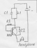
For example below oscillator circuit is very popular in simple rf tranmitters but i couldn't work it :( i don't know why:(
C1=1 uF
L1=3 mH
Transistor is NPN
R1=100 KΩ
C2= doesn't matter?only for feedback, isn't it?

Acording to my calculation oscillation must be about 3 KHz and if i add a headphone between emiter and negative side of power source i must hear the sound but no sound.Where is the wrong?
 

Attachments

  • simpleoscillator.png
    simpleoscillator.png
    99.1 KB · Views: 190
I believe you are looking at a circuit similar to the attached. Similar one transistor oscillator circuits can be found here.

Note the outputs require an impedance of 50K Ohms or greater to actually work and the voltage needs to be greater than 10 VDC. Circuits like this can work but they are very fussy sometimes about the components used. If something like that is what you want I suggest you read the link. I cannot say if those circuits actually will work as I have not tried them.

Ron
 

Attachments

  • Oscillator Simple.gif
    Oscillator Simple.gif
    9.7 KB · Views: 166
The circuit you're looking at is a VHF oscillator, I've never seen one used at audio frequencies, in fact you don't normally use inductors at all, as they are MUCH too large. If you need sinewaves, try phase-shift or wein bridge oscillators.
 
Thanks already my purpose is creating high frequency but firstly i must sure that is it working? for this reason i'm making my calculation acording to can hear frequency if it works i will change capacitor value so frequency will rise but anymore i know that

I've never seen one used at audio frequencies, in fact you don't normally use inductors at all, as they are MUCH too large.

Well , Does my circuit design work???
 
Thanks already my purpose is creating high frequency but firstly i must sure that is it working? for this reason i'm making my calculation acording to can hear frequency if it works i will change capacitor value so frequency will rise but anymore i know that


Well , Does my circuit design work???

I wouldn't have thought so, it's fine at VHF, but as I said I've never seen one attempted at audio.
 
I made a very short search on the Internet and found this interesting page:

**broken link removed**

Audio and RF oscillators RARELY share the same design concept.

Inductors generally become more efficient as the frequency rises (less coil turns, air rather than iron core), so LC audio oscillators are more difficult to design.

RC (coilless) circuits (Wien bridge, twin-tee, phase shift) are far more suited to audio rather than RF.

You can also google for "FM transmitter" or "VFO" and find many more oscillator circuits.

You can finally do some googling on "QRP". QRP are acual low power amateur radio transmitters that can be easily used as good quality sine wave RF oscillators.
 
Last edited:
Hmm.. thanks i changed my opinion but i'm still undecided.I exemined many circuit but i couldn't see any different between they and my design.for example i rised the frequency to 290 Khz and there is no sound in am radio.
 
Hmm.. thanks i changed my opinion but i'm still undecided.I exemined many circuit but i couldn't see any different between they and my design.for example i rised the frequency to 290 Khz and there is no sound in am radio.

I've already told you TWICE, such designs are used in VHF oscillators, NOT in audio, and NOT in LF oscillators.

It 'may' be possible to get it to work, by very careful design of the tuned circuit, the feedback capacitor, and the resistor values - but presumably there's good reason you never see it used at low frequencies? - for VHF use it's dead simple to get working.

Perhaps you would care to tell us what you're trying to do?, and we could suggest suitable oscillator types?.
 
Hmm.. thanks i changed my opinion but i'm still undecided.I exemined many circuit but i couldn't see any different between they and my design.for example i rised the frequency to 290 Khz and there is no sound in am radio.

First, listen to what Nigel is telling you, especially explaining your goals with this project.

Next:

my design.for example i rised the frequency to 290 Khz and there is no sound in am radio.

AM radio here in the US is between 550 KHz to 1.6 MHz. A carrier frequency is AM (Amplitude Modulated) but the carrier frequency is between 550 KHz and 1.6 MHz. I don't know what the AM radio band is in your location but I can't see an AM radio picking up an RF frequency of 290 KHz. Unless your receiver is capable of receiving 290 KHz. How do you even know that the actual frequency out is 290 KHz. as it would be a function of the components used and short of a scope or frequency counter you would not know the frequency.

You really need to understand what Nigel is telling you and answer his questions. Also, the link I provided earlier shows a few sine wave variations.

Ron
 
Last edited:
Two potential problems with the circuit. First is resistance in a 3 mH coil along with associated low Q resonating it with a 1 uF may result is not enough loop gain for oscillation.

Second, is headset resistance may also reduce loop gain below point needed for oscillation.

A multi-section R-C phase shift oscillator is easiest for sinewave output. It is important for a sinewave oscillator that transistor does not go into large signal swing saturation.

If you are doing this for proof of concept for a higher frequency RF oscillator you won't be proving much since the component Q's, and transistor gain will be so different.
 
I'm trying listen it in LW band.It is 150-340 KHz.This time i understood :) i want to make a simple transmitter (amplitude modulation).Many simple transmitters includes only oscillator and mic. input isn't it?Can you tell me what must be the values of components to work it?

By the way i'm using this for calculation.

**broken link removed**
 
Last edited:
Many simple transmitters includes only oscillator and mic. input isn't it?Can you tell me what must be the values of components to work it?

Use the values in the designs you've seen - which ALL work at VHF - you can't just use it down at longwave, where FM would be useless anyway, and the AM modulation provided is only a tiny amount.
 
Where will you find an old crystal earpiece today? They were used 50 years ago.

The OP may not be able to find an "old crystal earpiece" today, but can very likely find a new piezoelectric earphone, AKA crystal earpiece, today at a great many locations.
 
What uses a piezo earpiece today? The cheap scanning radio at The Dollar Store uses the same 32 ohm dynamic headphones as cheap MP3 players.
The cheap headphones that are given out on airplanes are also low impedance dynamic.

I think the AM radio circuit that uses a "crystal earpiece" is very old.
 
What uses a piezo earpiece today? The cheap scanning radio at The Dollar Store uses the same 32 ohm dynamic headphones as cheap MP3 players. The cheap headphones that are given out on airplanes are also low impedance dynamic.

Really? I just checked Google and found them running from $3.58 up to $129.99. But maybe all those suppliers were selling something other than the advertised crystal earphones. Gosh!

I think the AM radio circuit that uses a "crystal earpiece" is very old.

Er, ah, given your response in your post 15, the OP posted a transmitter schematic with a crystal mic, not earpiece.
 
Status
Not open for further replies.

Latest threads

Back
Top