Okay i got it all connected now, but must "debug" the connections probably, because something "short circuits" the XR2206 signal completely to flatline when i scope the XR2206 output.
Just to make sure i understand the symmetry of the bridge arrangement, are the 2 amplifiers identical or does the lower one need to have the transistors swapped?
I have also 2 questions concerning your diagram in post +47 and the load connection.
Is the 1000uF cap an AC cap, and if not what is the polarity?
You symbolized a GND symbol close to the output.
As i understand it the load is completely floating between the 2 amplifier outputs or does it need to be grounded and if so then at what side?
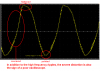
Spice Simulation of the circuit only shows 4 V Peak voltage at the output:
**broken link removed**
The circuit :
**broken link removed**
Just to make sure i understand the symmetry of the bridge arrangement, are the 2 amplifiers identical or does the lower one need to have the transistors swapped?
I have also 2 questions concerning your diagram in post +47 and the load connection.
Is the 1000uF cap an AC cap, and if not what is the polarity?
You symbolized a GND symbol close to the output.
As i understand it the load is completely floating between the 2 amplifier outputs or does it need to be grounded and if so then at what side?
Spice Simulation of the circuit only shows 4 V Peak voltage at the output:
**broken link removed**
The circuit :
**broken link removed**
Last edited: