Continue to Site

Welcome to our site!

Electro Tech is an online community (with over 170,000 members) who enjoy talking about and building electronic circuits, projects and gadgets. To participate you need to register. Registration is free. Click here to register now.

  • Welcome to our site! Electro Tech is an online community (with over 170,000 members) who enjoy talking about and building electronic circuits, projects and gadgets. To participate you need to register. Registration is free. Click here to register now.

Old Generator power low

Status
Not open for further replies.
I don't think I would be quick to short anything to ground. If possible I would measure the forward voltage drop across one diode then the other. Typically I would guess you should see about 0.6 Volts. That should be stable. My problem with your symptoms was the diodes were breaking down in my case. You can give your other thoughts a try. Without seeing a schematic I just don't want to suggest grounding anything.

Ron
 
Last edited:
I have not came across it on generators but I have seen it a number of times on old welders where all the diodes test good but when put on a load bank one will go open after it warms up and as soon as it cools down its good again.
Its very frustrating to try and find unless you have a O-scope and can watch the actual waveforms across each diode and the output lines. If one diode goes out its wave form signature is very obvious.

Besides its about all you have left that can create a low output voltage yet not completely drop out. The skipping brush would give a fairly noticeable sparking being the rotor is basically a good sized inductor on a DC circuit. It would naturally tend to give off a very noticeable spark if the commutator rings are skipping.
 
Ron - I agree about taking anything to ground as an experiment. There is a schematic posted early in this thread. Note that the BLUE wire is a centertap in the rotor winding. The feeling is that the cap is just a filter in the circuit. If it were to short I'd have no field voltage. I have removed the cap from the circuit with the genny running and the output did not change. Diode tests are next.

TCMTECH; My current thought (thought de jour?) is that one of the diodes is opening so we agree on that. The diodes are the stud mount type, screwed into the chassis of the genny. I'll remove the field wire from each diode. I'll attach a temporary wire to each diode and route it out of the genny via a large access hole. And I'll route each field wire out through the access hole. The connections will be made using test leads. When the genny field voltage drops from 72vdc to around 35vdc, I'll disconnect the diodes one at a time. When I disconnect the failed diode nothing will change. When I disconnect the remaining good diode I expect the field voltage to drop to zero - or at least it will change significantly. The thought is that removing a failed diode from the circuit won't do much. Removing a working component from the circuit will change things dramatically. Nothing will be run to ground.

To All watching this thread. I'm only going through all of this stuff in hopes that someone with similar issues is reading along and learning. I found out early on that these little generators are sort of a mystery and there isn't much troubleshooting information available. Through this testing and posting of results I hope someone increases their knowledge base. I know that I am learning.
 
I looked very closely at the marking on the diodes to be sure I got the orientation correct. The diodes are shown and the connector between the windings section of the genny and the bell end (front panel) is corrected. Oh, and the blue wire now looks more like a center tap. It's getting better. It's been a lot of years since I've needed to make a schematic. Just a simple circuit diagram usually does what I need.
Thanks for your patience.
Mark
 

Attachments

  • AG-Schem.jpg
    AG-Schem.jpg
    45.4 KB · Views: 235
Last edited:
Now your schematic makes much more sense!
You are right about the limited amount of troubleshooting information on the small portable generators from years ago.
When your done this will be a thread likely worth doing a rewrite of and having ETO post it permanently in the RE or AE section of the forum as a referance thread.

One note for you is that most of the small generators are usually set for about 62 - 63 Hz no load and will usualy pull down to around 57 - 58 Hz at its full rated load if the governor is still good. Its how I have always set up welder generators.
 
Schematic does make more sense but the outer brush line (Yellow) is connected to ground in the schematic and continues through a diode to ground. This makes Anode and Cathode of one diode both going to ground. I figure that is a boo boo. The diodes conduct on alternate half cycles. The picture shows things pretty clear.

Doesn't seem the case here but sometimes a diode designation (part #) will be followed by a R and the R designates the the diode is reversed with the anode and cathode as to which is the stud. This is frequently seen when the enamel inset at the center terminal is a different color. Like one is yellow and one is blue for example. The same part number is shown for both and the drawing makes sense less that ground lead I mentioned.

I am curios what will fix this thing. :)

Ron
 
Ya got me. Gotta fix the schematic - I messed up the ground circuit. And I'll remove the diodes and check for an "R" designation on the marking. I did a test and I'll post the nonconclusive results at that time. Gotta go get some lunch now. But I'LL BE BACK!
 
Schematic does make more sense but the outer brush line (Yellow) is connected to ground in the schematic and continues through a diode to ground. This makes Anode and Cathode of one diode both going to ground. I figure that is a boo boo. The diodes conduct on alternate half cycles. The picture shows things pretty clear.

Doesn't seem the case here but sometimes a diode designation (part #) will be followed by a R and the R designates the the diode is reversed with the anode and cathode as to which is the stud. This is frequently seen when the enamel inset at the center terminal is a different color. Like one is yellow and one is blue for example. The same part number is shown for both and the drawing makes sense less that ground lead I mentioned.

I am curios what will fix this thing. :)

Ron

I'm back. The schematic is revised again. I'll post it as REV C. When I get this done it will be a real art form! And perhaps it will be typical and of use to someone else. The diodes are "R" type and the ohmmeter shows about 4 megohms with the RED lead on the ground threads and the black lead on the solder terminal. I changed the schematic to show how it works electrically. This is making more sense now. Oh, and I had the brushes wired wrong on the schematic. Don't know what happened there. It should be better now.

At the genny, I removed the winding leads from both diodes. I routed the winding leads out through access holes in the front panel. I soldered 24" wires to the diodes and routed those wires out through the access holes in the front panel. I connected the winding leads to the diodes using test leads.
With the genny running I had to work quickly as I only have 2 minutes run-time before it goes into fail mode.
Field is 72vdc NO LOAD.
With a 6 amp load the Field is 74vdc. Output is 127VAC and 6 amps.

I removed the test lead from each diode - one at a time. With one diode removed the field drops to 35vdc, Both diodes give the same result. I've seen that 35vdc field every time the genny fails. Removing both diodes kills the field - as expected. The output on the genny is still correct but I'm starting to see a little fluctuation in the DC voltage on the field. It's minor but it's becoming unstable.
At about two minutes the genny went into failure mode. A field test shows the typical 35vdc and I have 3 amps, 90vac.
I removed each diode connection, one at a time. Removing EITHER diode results in the field voltage dropping to 0vdc. I expected that removing a bad diode would have no effect and removing the other (good) diode would kill the field.
So what is the common denominator of this? I expected to see 35vdc in fail mode. I figured ONE of the diodes was opening up under load. It's not likely that BOTH diodes are going into the same fail mode at the same instant. That tells me it is NOT a diode. I'm befuddled now.
Again, what's common? The inner brush is wired directly to ground. The (-) terminal of the cap is wired directly to ground. If the brush was losing contact the field would go to 0vdc. There is no spark at the brush.
What about the cap. If it shorts, the field collapses to 0vdc.

I'll remove the cap from its ground terminal and wire it through test leads. I'll run it until failure and then remove the cap from the circuit to see the results.
I read somewhere that the value of the cap is used to set the voltage of the generator. If the cap is changing value dramatically but not shorting and not opening . . . Hmmm. If the genny is in failure mode and I remove the cap from the circuit and the field voltage changes but neither returns to 74vdc nor kills the field what do we know?
I'll be back In the meantime, look at the schematic again and grade my paper.
 

Attachments

  • AG-SchemC.jpg
    AG-SchemC.jpg
    51.5 KB · Views: 272
By chance can you externally power the rotor? If you have a solid near 75 volts going to it and it still does it then you know its either some weird diode break down effect or a partial short in the exciter windings that acts up when the winding temp starts to rise.
I am now half tempted to wonder about a dried out capacitor being the cause. That can have possible effects on how it is working in the circuit as well. If it looses its connection internaly it could cause the voltage filtering effect it does to drop off. That would also cause problems with the rotor voltages being the power feeding it drops from near peak to the RMS of the exciter coils.

Only three revisions to get your schematic right? :rolleyes:

You are overqualified to work here! :D
 
I vote for the capacitor going bad. BTW I think you drew the diode backwards, the way they are drawn it would clamp the field at .6v
 
I vote for the capacitor going bad. BTW I think you drew the diode backwards, the way they are drawn it would clamp the field at .6v

TCMTECH I've got something this time. I had a gas leak between the tank and carburetor. New gasket. What's up with that. Answer; I didn't secure the bolt at the tank bracket so the tank was mounted to the vibrating carb with no physical support to the engine block. No wonder it leaked. Secured the bolt and the leak quit. Funny how that works.

Down to the business at hand. 75 volts would have proven the diodes if the failure was the diodes. If the diodes aren't the issue, we'd still be scratching our heads. And believe me when I say my head is darned near wore out from the scratching??!!

I offered early on that a big ole cap like that that's 35 years old and been stored in old barns and sheds in northern Indiana should be in bad shape. Didn't know if that was true, but it shoulda been. But I needed a test to determine WHAT is the cause of the drop to low output. So we've been here for a week.

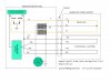
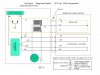
Neal, the cap thing in the schematic - they're drawn the way they work, not the way they look when I look at the cap in the photo (post # 10). It's the R at the end of the part number - MR 1124R that designates a reversed attachment. Anode and Cathode are switched. That's a cruel joke to play on an old guy. That tidbit came from Ron a couple of postings ago. So You think it's the cap too? Well here's the latest test result.

Removed the ground lead from the cap and attached a test lead to the eyelet and taped it up. Routed the test lead out of the housing through an access hole and grounded the lead to the chassis. Started the genny and noticed that the clip lead inside the head was rubbing against the rotor and getting beaten to death so I fixed that. And the test resumed.
With the genny running properly, 130 vac at 6 amps. 72 vdc at the field.
Removed the ground from the cap with the genny still running properly, 125vac, 5.5amps 53vdc.
Bewilderment followed by more head scratching.
Grounded cap and I get 5 more vac and another half amp.
So I set my load to 12 amps with the cap in place.
Field 74vdc, 127vac, 12 amps.
Removed the cap ground; Field 58vdc, 123vac, 10.5 amps
Removing the cap does drop the field and output but its entirely usable. And I'm 4 minutes into the test and the genny is still working great! So I left the cap ground off for a while.
At 5 minutes I'm feeling pretty good. The gas tank isn't leaking next to the hot muffler. And the AC output is holding steady.
Interesting stuff follows; I grounded the cap and waited. about 15 seconds later the engine started to surge slightly, then progressively worsened. The ammeter was fluctuating and the field was dropping. So I removed the cap ground. Gently it all settled back to normal. Field, and AC out resumed a somewhat low but entirely usable ouput and the engine surge stopped. Cap grounded - surge et-al. No cap ground - normal.

The BOTTOM LINE. Gents, I'm thinking the Electrolytic Capacitor is gone. Judging by the size spark I saw when I grounded the cap, there's a lot of current there. I can now replicate failure mode. I can predict what will happen and when. And I can prevent it. Now I need to locate a new cap of the correct size. I'd rather get one locally but if all else fails, McMaster-Carr has them. And I guess I need a new test lead boot too. Nuts.
I'll be back . . .
 
Last edited:
The attached link has caps you can order on-line. Electrolytic Capacitors - 70 µF to 159.9 µF

If you can fit the size, a motor run cap will hold up better to the heat, but a lot more expensive. **broken link removed**

The heat that an electrolytic is going to be subjected to in this application is bad for its longevity.

Don't use motor start caps., The are back to back electrolytics used only for short motor startup period.

If you just want to try a cap to see if it fixes your problem, an old switching power supply (like old computer power supply) will likely have a 200vdc+ rated electrolytic cap in it you can scronge out.
 
Last edited:
tcmtech,
Ya got a whole bucket full of them huh? I'll trade you a brand new Briggs and Stratton exhaust valve for a cap! I ordered a new valve not even considering that the new one might have the wrong type retainer. So I have a spare $8 valve. There goes retirement. Gotta work another year.

I'll tell you and the other guys following this thread - this has been a good time. Of course it's not over until the unit runs and proves itself. Then I have to decide if I want to put new brushes in it and do I want to put a quieter muffler on it?? I bought it with the idea that I could recondition it and sell it. There's something cool about an authentic old piece that's been out of production for a long time. I like to keep them just as they were made, and they weren't quiet back then. Is Ag-Tronics collectible? Not by me, but if someone watching this thread is interested we can talk.
I pulled the head and decarboned everything, checked the valves and seats to ensure it was able to run correctly, removed the carb and cleaned it, got the rust out of the fuel tank, put new gaskets on it and put it all back together. Then the genny started dropping out after two minutes and the fun began. I've learned a ton about these little guys over the past week or so. At this point I hope to come close to breaking even on the money. I have a "real" generator for use in a power outage and I paid $120 for a 2400 watt Generac / Briggs unit that is just a great little toy generator. With this much time and effort in the Ag-Tronics I sort of hate to sell it. It certainly has been a good learning tool. It's a project piece.
One thing is for certain. I'll pull the information that I learned from this and create a test manual with field voltages and all that stuff. I may not be any smarter than I was but I'm certainly better informed!
I guess there's a football game on tonight? Being in Indiana I guess I should watch it. Or I can do something else and I'll hear about it tomorrow.
 
Last edited:
I'll tell you and the other guys following this thread - this has been a good time.
One thing is for certain. I'll pull the information that I learned from this and create a test manual with field voltages and all that stuff. I may not be any smarter than I was but I'm certainly better informed!
I guess there's a football game on tonight? Being in Indiana I guess I should watch it. Or I can do something else and I'll hear about it tomorrow.

Hi Mark,
I only found this thread tonight and had a good read thru ;). Your quote above about creating a test manual would be great. Once you've done it if you like I will put in in the RE projects forum as the quality of the information from this thread shouldn't be lost.

Regards Bryan1

P.S. just PM me if you like if your interested
 
Hi Mark

If you plan to put something together on this adventure the attached image may help a little. It consist of your image plus another image of a 120/240 volt unit. Note that things haven't changed much as that design has been around and used for decades.

I am still betting on diode breakdown but then too, I would have bet on the Colts.

Edit: EX2 has an extra wire that should not be in there. When I placed the 2 drawings on a single canvas I lost a line. Well I guess I found it as wire :) . That is not a wire but an inadvertent line.

Ron
 

Attachments

  • Generator Ckts..jpg
    Generator Ckts..jpg
    112.3 KB · Views: 201
Last edited:
Ron, I think that publishing both is a good idea. My "schematic" is more of a combined wiring diagram and schematic. A lot of folks with no real training find the diagram very useful. Yours is obviously more correct. Once I get all of this information gathered and put together I will be submitted and might prove to be a resource for others with similar problems.

And about that diode. It's logical that the field voltage is 70vdc when all is well but is 35vdc when I pull one of the diodes out of the circuit. It goes from a half wave rectifier to a quarter wave so the field is cut in half. Logical. What screwed me up was that in failed mode, with the field reading 35vdc I could remove either diode and still have 35 vdc on the field. I expected to pull one and have no change and pull the other and lose the field entirely. That would indicate a failed diode.
As it is, I can run the genny until the unit starts to fail and remove the cap and it stabilizes at the correct output. The output follows my inserting and removing the cap. If I remove the cap and stuff it into a snow pile for a minute and then put it back in circuit, the genny runs fine until the cap gets warm again. I had left the genny in my cold shed overnight and started it up really cold and it ran for 8 minutes - until the cap warmed up. Looking at the aluminum case of the cap, it got pinched pretty good when someone installed the steel clamp incorrectly. The aluminum case has a well defined dent in it. And it's likely that the two foils with the dielectric between didn't appreciate that move. Anyhow, I'm in search of a new cap locally. I'll report back when I have it replaced.
Mark
 
I'm back

Well I'm back with my little generator. I finally did find a capacitor and it's installed and the test is done.
The field voltage has changed with the new cap.
I talk too much so here's what I know to be true. If you have a clue, I'm listening.
The Field is now 65vdc. It drops to 32vdc when it fails.
At half the field voltage I get half the AC output
The genny ran for 8 minutes before failing. With the old cap I get 2 1/2 minutes of run time before the genny goes to low output.
When the genny failed, I shut it off for one minute and restarted it. The field was good for a few seconds, then failed again.

The following is from tests prior to the new capacitor.

When the genny is running correctly, removing either diode drops the field by exactly half.
In fail mode the field is exactly half.
In fail mode, removing either diode kills the output entirely.

If I remove the capacitor when the genny is in failed mode, the correct output resumes at about 90% of it's normal output.
I removed the cap and ran the generator for more than 8 minutes and it never did fail with the cap removed from the circuit.

I'm sure I'm looking at the answer and I just don't see it. Maybe the new cap is physically too small, but it meets the specifications and it's in a major air flow area - and it's only 27°F outside.
 
Well if removing one diode at a time and the output drops 1/2, then your diodes and field have to be ok.
And it runs at 90% without the cap, so I think you have a new cap that maybe breaking down or something. I'd try another different manufacturer cap.
 
Well if removing one diode at a time and the output drops 1/2, then your diodes and field have to be ok.
And it runs at 90% without the cap, so I think you have a new cap that maybe breaking down or something. I'd try another different manufacturer cap.

Thanks Neal. I was beginning to doubt my sanity. tcmtech says he has a bucket of them. Maybe I'll send him postage and he can send me a couple. I'll PM him

Thanks Neal
 
Status
Not open for further replies.

Latest threads

New Articles From Microcontroller Tips

Back
Top