Continue to Site

Welcome to our site!

Electro Tech is an online community (with over 170,000 members) who enjoy talking about and building electronic circuits, projects and gadgets. To participate you need to register. Registration is free. Click here to register now.

  • Welcome to our site! Electro Tech is an online community (with over 170,000 members) who enjoy talking about and building electronic circuits, projects and gadgets. To participate you need to register. Registration is free. Click here to register now.

Low loss power OR-ing with MOSFETs & Op Amps

Karklebapper

New Member
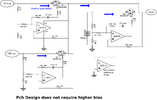
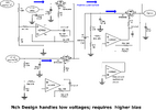
This is a couple of circuits which I devised maybe 16 years ago. The Pch design (without a higher bias) does require a rail-rail input op amp. But the Nch design with higher bias can use a general purpose op amp such as LM324. These circuits will select the highest of the available inputs, even when the voltage differentials are small, such as 20 mV for example.

Using op amps like this, the circuits are slow so will require at least many microseconds to react.

With low Vos op amps and adequately sized FETs this circuit can work well with voltage drops (and input differentials) in the low mV for example.

It has been many years, but I built and tested these circuits pretty much as shown many years ago. I might have a board somewhere...
 

Attachments

  • Nch-01.png
    Nch-01.png
    157.9 KB · Views: 130
  • Pch-01.png
    Pch-01.png
    146.6 KB · Views: 120
This is a couple of circuits which I devised maybe 16 years ago. The Pch design (without a higher bias) does require a rail-rail input op amp. But the Nch design with higher bias can use a general purpose op amp such as LM324. These circuits will select the highest of the available inputs, even when the voltage differentials are small, such as 20 mV for example.

Using op amps like this, the circuits are slow so will require at least many microseconds to react.

With low Vos op amps and adequately sized FETs this circuit can work well with voltage drops (and input differentials) in the low mV for example.

It has been many years, but I built and tested these circuits pretty much as shown many years ago. I might have a board somewhere...
I don't see a question. Are you hoping to get feedback on these circuits or are you just hoping to save the world by sharing these designs?
 
To aliarifat794:
When I designed this, I was an applications engineer for ADI. Another engineer was designing a demo board which could be powered by +5V USB or an on-board battery (and I think that an external +5V power supply was a third option.) He wanted the board to automatically select the highest of those inputs, but he could not afford the voltage drop of a PN or schottky diode. I designed these circuits to meet that requirement. I believe this is a common sort of requirement.

Many of these are intended to do similar:


The difference is that my design allows you to do it with "common garden variety" components which are not application-specific. When I did the design, ADI had no such offering as might have belonged in the list at the above link.

+++++++++++++++++++++++++++++++++++++++++++++++++++++++++++++++++
To ZipZapOuch:
This is a forum and I did not know that "needing help" was a prerequisite for originating a thread. I am open to any sincere and serious discussion about the circuit design which I have presented. I wonder about the note of sarcasm in your post, and whether I have offended anyone? I note that there are many other posts on this website which simply present and discuss circuits. In fact I noticed another one for a design which is functionally similar. I wonder why you picked on mine...

Beyond that, I like your avatar name. I hope it is intended only as humor rather than something which happens to you often.
 
Last edited:
Welcome to the forum.
Ignore the potshots.
Sometimes a poster here will get up on the wrong side of the bed and feel a little snarky.

But to the point, most TS's (thread starters) are here to ask a question, so if there's no question, the post is sort of hanging in the air from our point-of-view.
So if your post is just to show some information or a circuit of possible general interest, then a sentence to that effect will eliminate the uncertainty of the reason for your post, and likely avoid any sarcastic replies.
 
I like your Pchan version better.
Many times one doesn’t have the luxury of a higher bias voltage. And unless one is switching large currents, the higher RDSon of the Pchan Mosfet shouldn’t be too detrimental.
 
You are probably correct in that the Pch design is more useful. I think that +5V USB is the most common sort of use case, and higher bias voltages will seldom be available. Of course one could add some sort of boost converter but that probably does not pay off unless we are dealing with a high power or high current system. I am just prejudiced in favor of Nch mainly due to the lower Rds "ON", but also because there is no need for a Rail-Rail op amp once you have that higher supply voltage.
 

Latest threads

New Articles From Microcontroller Tips

Back
Top