Electro Tech is an online community (with over 170,000 members) who enjoy talking about and building electronic circuits, projects and gadgets. To participate you need to register. Registration is free. Click here to register now.
Welcome to our site! Electro Tech is an online community (with over 170,000 members) who enjoy talking about and building electronic circuits, projects and gadgets. To participate you need to register. Registration is free. Click here to register now.
As the tittle said I need help to draw a schematic based on this circuit . I tried to upload a couple of photos but it won't let me ... can someone help please ?
Are asking for help to "reverse-engineer" an existing circuit board by tracing the connections in order to draw a schematic diagram?
I post pictures here every day. What are you doing?
Do the following:
Click on the "Upload a File" button when posting
Navigate to the file you want to upload using the pop-up dialog, likely helps if it is an .jpg or .png
Click on "Open"
Now you have an option of inserting the contents of that file as a thumbnail, or full image.
I did both to show what they look like:
Note, if you click on the thumbnail, it opens into the full image in a secondary tab.
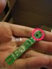
We'd need higher quality photos, for one thing. It looks like a basic board with a couple of LEDs and some current limiting resistors, but without knowing what it's used for specifically and where it came from, it's difficult to know for sure. More angles of the board would be nice too.
I will try to shoot more photos but this circuit board belong to one of my project cars . It is a side markers from the side of the car when you turn the signals ..it will blink and it's lit up when you turn your headlights on . All I can tell is there are 3 resistors in parallel and two 4 pin leds ( 2 neg 2 pos) and a diode ( not sure if it's a zener ).
An Melf Diode (Metal electrode leadless face). Have seen these in large LED strips from automotive in series with resistance before, tho usually an controller elsewhere to get different flashing results of such as in an relay cluster under dash.
Many types of methods used to do this, multi relays (one cancels out the other on blinking) or (an IC with an simple gate logic) or an simple copper slide switch located in the steering column signal lever. Usually the cheapest method would be used by an company due to mass production cost adding up only having to use some part cost components to meet safety standards usually regarding what year of production as these rules often changed.
As for what controls the light modes, that controller would have to be located elsewhere. Some are even in the 4-way flasher module as that gets removed the whole signal system stops, or at least that's what happened in some older mid 90's Mazda Protege DX types and some Nissan Sentra, others as well.
So careful hunting if that module would be wanted if it has one, just in case of potential no more turn signals or park lights if it's an incorporated module and something goes wrong. Also late 80's to early 2000's Toyota had everything in the Retractor control module including brake lights when pedal is pressed as also controlled the park lights with timer for courtesy lighting and main park light function vial relay control.
Reasons for the extra info, I think you may be after the LED operation including the blinking ability as well?
this is it . The whole purpose of having a schematic is I want to play with a different leds ( white , yellow etc ) and of course we all know they all have different voltages and there will be different resistors value as well ?
There are articles on many types of LED, and yes different color when mixed can vary the current rating on the lowest color part (potential overload when wired in series)
That board, looks to be two layer. Have to trace the paths to each LED, resistor connection, as the board is giving direction via being labeled topside. Then from the LED common onto where ever else.
----------------------------------
LED calculators exist online.
--------------------- --:Edited:- -Rant does not fit properly, so just some extra info Section below.
The LED voltage forward drop is needed mostly (if obtainable, some multi meters do not even show some LED's are there at all even if it is lit), then the desired voltage and its current capability (so not to drop its output via too much current draw) then the desired LED current, per LED. then finally how many connected in rows of series configuration.
Meaning so many number per row then on to the next resistor chained row (each row has its own deticated resistor in a multi row config), or an single row with a primary resistor could be done.
Different LED and size types and current ratings as with many types, 3mm are usually low current 10mA, tho can be made for higher current/Volt. And 5mm avg 25-30 mA max unless high power, then the rating just keeps on going like an 10W 900LM lamp bead that has 9 small LED cells in one casing that can harm the eyes.
Current rating can usually be determined via the size of an led for a starting point (which can vary and I am not completely aware of ratings for an unknown LED without an known datasheet that is not all ways possible to obtain a datasheet without knowing the LED such as those on that board per example).
However those types (on board) are usually bright type, as for high visibility and for an market view point there are countless types of LED's to a point of eventually hitting reality and eventually having an real number of how many types exist would be quite a chore.
My meaning is there are thousands to choose from with Volt/Current ratings.
The diode acts as an forward drop limiter as voltage can change on a vehicles electrical system via alternator and other electrical systems flooding random GND points, if I've gotten that correct. And can usually be located at the end of resistor rows before connection to the Common GND as appears on that board for most view point.
The LEDs with 4 pins might be made by Lumileds Luxeon and they call them Superflux. Their maximum allowed current is about 50mA to 70mA. Any normal 5mm diameter LED might burn out with that high current but Superflux LEDs are made in all colors.
I'm going to replace with different leds ( still 4 pins ) and of course the value of the resistors will be changed too but what I need is a schematic of the circuit . It's hard to believe that with a circuit like this I still haven't got anyone to help . I am sure that we have a lot of technicians and engineers in here but oh well ....
It's hard to believe that with a circuit like this I still haven't got anyone to help . I am sure that we have a lot of technicians and engineers in here but oh well ....
Engineers and technicians like to gather all of the information first before trying to pursue a solution. Try to be patient, and answer as many questions as you can.
Engineers and technicians like to gather all of the information first before trying to pursue a solution. Try to be patient, and answer as many questions as you can.
I understand sir but I've answered or provided alll the info that I know of the circuit and in the meantime I came up with this diagram and please correct me if I'm wrong ...
This site uses cookies to help personalise content, tailor your experience and to keep you logged in if you register.
By continuing to use this site, you are consenting to our use of cookies.


")
