Continue to Site

Welcome to our site!

Electro Tech is an online community (with over 170,000 members) who enjoy talking about and building electronic circuits, projects and gadgets. To participate you need to register. Registration is free. Click here to register now.

  • Welcome to our site! Electro Tech is an online community (with over 170,000 members) who enjoy talking about and building electronic circuits, projects and gadgets. To participate you need to register. Registration is free. Click here to register now.

New ICs are a nightmare

Status
Not open for further replies.

audioguru

Well-Known Member
Most Helpful Member
Texas Instruments has announced the OPA1622 stereo headphones driver IC. It provides plenty of output power into 32 ohms or higher, no distortion and no noise. It is wideband. Its supply can be as low as 4V.

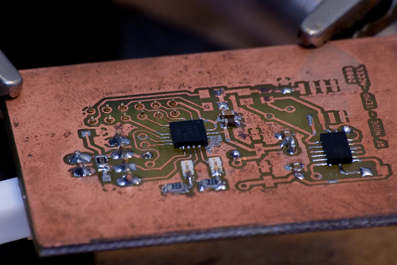
BUT, it costs $7.35 at Digikey today and they can supply only one if you want. It is so small that you can barely see it and its contacts (it has no pins) are half-a-millimeter-apart underneath it. Also on its bottom is its thermal pad that must be soldered to a heatsink somehow.

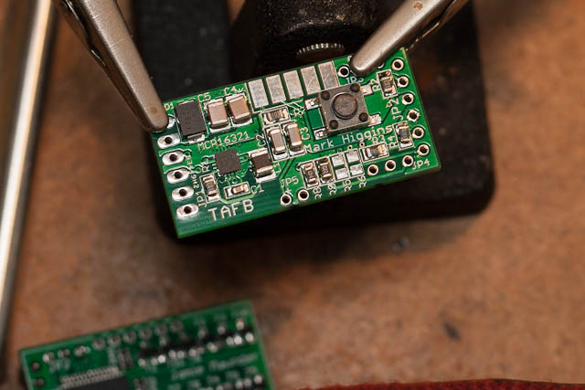
How can we use such a tiny little thing? I wonder how soon a little pcb from China will have it already to be used?
 
Well to use it you need a proper PCB with solder mask and use solder paste with stencil and reflow soldering. Companies don´t manufacture parts with the occasional hobbyist in mind, these chips are aimed at mass produced items like cell phones.
If you are very cerful you might get away with using a breakout board, pre tin it with soldering iron and use hot air and lots of liquid flux, it should seat itself nicely if the breakout is done correctly. But I agree the 0.5mm pitch is a major PITA for one time use.
 
Audioguru, Welcome to the New World, Through Hole Parts are OBSOLETE Now.
I Doubt Any Manufacture actually makes ANY Through Hole Parts anymore.
 
Oh for the good old days of the 741. :D

JimB
 
The world has gone to surface-mount technology, no longer intended to be soldered by hand. The size is reduced to allow higher circuit density on boards in a smaller amount of space. The package is flat with no leads, once again to reduce space but also to limit inductance of the pins, etc. The board is set up with pads, which are covered at the assembly house with solder paste. The component is then grabbed out of its tape by a robot and set down on the paste, which holds it in place. The paste is made up of flux and tiny beads of solder. The whole board is run through an oven and the paste melts--The flux burns off and the solder beads melt, soldering the flat pads on the bottom of the chip to the pads on the PCB.

As mentioned before, welcome to the future! Through-hole technology is all but obsolete for professional applications--90% of the circuitry I design and create PCBs for is surface mount. We don't really hand-solder here, we simply send the designs to the assembly house (in the case of the company I work for, one of our vendors manufactures the PCB and assembles it for us). SMD is hands-off and very easy for machines to build. Through-hole is more difficult to work with in mass production, making it practically obsolete in the industry.
 
I used a lousy old 741 and an LM324 about 46 years ago and never again. Then I used much better opamps for many years.
About 20 years ago I ordered through-hole CD4017 ICs and when they came as surface-mount I had the distributor replace them. I never used the surface-mount ones.
 
Looks like the future is dim for the bread board and strip board hobbyist, although the breakout board producers seem to have the SOIC, TQFP etc even SSOP forms covered , cannot see the paste and pads will work out, perhaps I will be too old to care by then ...
 
Never underestimate the ingenuity of hobbyists. I know a quite a few hobbyists that use surface mount devices all the time, and not just the young ones with good eyesight and nimble fingers. Lot's of old guys too. I've used a few of them myself. I can't say that I like using them; they're a pain, but often there's no other choice. Like any new technique you make a terrible mess the first few times you attempt it, but then you get better and better. And yes, you'll have to buy or make some new equipment.
 
the smallest I have been able to use in a 10-PIN DFN 2 mm x 2 mm x 0.85 mm etching that board with toner tranfer was just the fun part, soldering it was even more fun...:banghead:
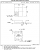
, Now I learned to check the size on a print out first.
 
Packages like SOIC, SOT, and even TSOP can be hand-soldered fairly easy.

But the leadless packages (and there is a whole alphabet soup of those) are essentially of limits to hobbyists.
If one requires to use one of them, better find a breakout board from Sparkfun, Adafruit or even (gulp!) Ebay.

I just built a temperature/humidity sensor using the HDC1008. If one has ever attempted to build an analog temp/RH sensor, you know it is a challenge, specially for the RH portion.
The HDC all that requires besides the chip itself is I2C communications with a microprocessor, and an ultra-simple algorithm to convert to human readable temperature and humidity.
Specs are great, and the price surprisingly cheap.

But with a DSBGA (8-bump), 2.04 mm x 1.59 mm package, it is impossible to hand solder. Fortunately Adafruit has a breakout board.
 
For the RN42 Bluetooth module, not precisely an SMD IC,

RN42.png


the datasheet mentions:

Castellated.png

which are located 1,2 mm apart.

I know a guy, who soldered one, in a somewhat unusual way to have it ready during a long weekend so he could start testing his code to command it with a micro in less than 48 hours.

He is 69yo, suffers of trembling hands most of the time when soldering and has very tired eyesight.

At 19 USD apiece, damaging one was not the nicest option.

But, in spite of all against, I succeeded.

SANY9343.JPG


SANY9338.JPG


SANY9339.JPG
 
I try to avoid these .5mm spaced chips just because they go beyond the specs of the cheap chinese PCB manufacturers. .2mm spacing between pads is out of spec for itead/seeed/elecrow... Being careful I can make my own etched PCB's for these, which I've done before.

Soldering is not hard. A small amount of solder paste and hit it with the hot air or put it in a oven and it's fine, seats itself.

Don't be afraid of it, it's not that hard, just takes a bit of experimentation.

Not DFN/DRC size, one step up, but it's the only picture I have.
20090809-rf-node-photo-002.jpg


EDIT: I guess I'm wrong about this being out of spec with itead/seeed... Just looking at some boards I've made and noticed I used a MCP16321 which has .5mm spacing. I know I tried a DFN recently and it gave errors on the DRC.
EDIT Again: I remember now. I had to edit this footprint for the MCP16321. the 0.2mm spacing is out of spec, but if you make the pads slightly under sized, 0.25mm you can get 0.25mm spacing between the pads which works.

20120606-throttle-001.jpg
 
Last edited:
I am not the only one who will have problems soldering that tiny IC to a circuit board. Product manufacturers also might have problems because the Mechanical Data page on the datasheet says, "This drawing is subject to change without notice"!
There are tiny "side pads" where the bottom solder pads fold around the edge and up the sides for a whopping 0.2mm.
 

Attachments

  • tiny IC package.png
    tiny IC package.png
    49.8 KB · Views: 203
audioguru ... perhaps mounting that little begger upside down and connecting with thin wires ..
 
I am not the only one who will have problems soldering that tiny IC to a circuit board. Product manufacturers also might have problems because the Mechanical Data page on the datasheet says, "This drawing is subject to change without notice"!
There are tiny "side pads" where the bottom solder pads fold around the edge and up the sides for a whopping 0.2mm.
That's not a problem if you're doing reflow or wave soldering (as most professional board assemblers do). The drawing is subject to change, but when it is a new rev will be released. That rarely happens, it's just a legal statement saying that the manufacturer isn't liable for any issues that may arise if the user has an outdated datasheet.
audioguru ... perhaps mounting that little begger upside down and connecting with thin wires ..
Ah yes, the infamous dead bug style...
IMG_0667.jpg
 
Status
Not open for further replies.

Latest threads

New Articles From Microcontroller Tips

Back
Top