Hi Max,
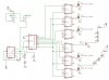
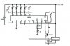
The 1uf cap is important because its rising charging voltage is what is indicated by the LM3914 voltmeter. I was going to use the 7th output of the LM3914 to discharge the cap but realised that when the cap begins to discharge, the 7th output signal disappears, and the cap would never discharge to zero volts.
So I added a 555 oscillator at the last minute that would use its discharge pin #7 to discharge the 1uF cap to zero.
The transistor is configured as a constant current source, to charge the capacitor linearly with time. You could use just a simple resistor to charge the cap instead of the transistor, but then the cap would charge exponentially, starting with a very fast voltage rise then slowing down.
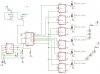
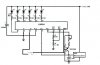
Your revision to my circuit shows the LM3914 indicating the voltage of the cap in the 555 oscillator. That would be awkward because the 555's cap normally operates at between 1/3 to 2/3 of the supply voltage. So the LM3914 must have its low and high voltage points also the same. When power is applied by your turn-signal switch, the cap will be at zero volts and take some time to reach the 1/3 supply voltage that would turn-on the LM3914's 1st LED. A very noticeable delay.
My 1uF cap would start charging and the LM3914 would indicate its voltage immediately when power is applied by your turn-signal switch.
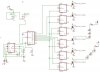
But now I realise that the very 1st time period of the 555 is longer than all the rest. That would cause the 1st sequence to end with all 6 LEDs lighted and a delay before they are turned off and the next sequence begins. I'll think about how to fix that.
Hi Willi,
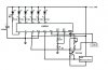
The only time the LM3914 needs Fets is when it is driving high-current light bulbs. It can directly feed 20mA to the LEDs with no problem.