Continue to Site

Welcome to our site!

Electro Tech is an online community (with over 170,000 members) who enjoy talking about and building electronic circuits, projects and gadgets. To participate you need to register. Registration is free. Click here to register now.

  • Welcome to our site! Electro Tech is an online community (with over 170,000 members) who enjoy talking about and building electronic circuits, projects and gadgets. To participate you need to register. Registration is free. Click here to register now.

Need help in 88-108MHz preamp circuit!!

Status
Not open for further replies.

rahulan999

New Member
Hi friends,
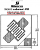
I'm building an fm-band preamp and the circuit is here:-
https://www.uashem.com/pageid-476.html
I have bought 2*2N3819 tr for this purpose already which was some what costlier for me, anyhow adjusted. But when I was beginning to assemble, I got a too much confusion on the pin-outs for transistors in the circuit. Means the source and drain for the transistors not mentioned at all!!. Arre..It's too much irritating me..as I can't experiment with the JFET's that are subjected to static electricity....may die off!. help me.
 
Thanks for ur response!! But what I exactly mean is in the circuit diagram they didn't mention the terminals. Plz look on to the circuit and can u tell me what are all the source and drain terminals of both FET's by connecting-to component wise.

Also arre...I have found that the datasheets of philips and fairchild for 2n3819 mention different pin configurations. In fairchild datasheet, its top to bottom source,gate and drain!. I'm too much confused. Help please.
 
Hi Rahulan999,

That's exactly what I meant:

On the schematic the connections for both fets are:

From top to bottom Drain Gate Source.

I'm aware about the second problem, I'm afraid I can't
help you with that.

on1aag.
 
The circuit diagram is just a representation.

The top node in the diagram is Drain.
The middle node in the diagram is Gate.
The bottom node in the diagram is Source.

When building the circuit you are not always going to connect nodes by the way they are drawn but by what you can capture from the diagram as of functionality.

When any kind of transistor is represented in a diagram if the gate is show on the left side of the transistor the order from top to bottom will be drain-gate-source, in some cases the gate might be shown to the right of the transistor - which will be an inverted drawing-, then the order from top to bottom will be source-gate-drain.

So the Drain-Gate-Source order of representation in a diagram does not have to be the same order in the actual manufactured piece.

Is this what you wanted to learn?
 
Last edited:
Thanks. I think fairchild has got some mistake over that..otherwise I should admit that what I hav got is not a fairchild one! I will go on with philips pin configuration. You have got any testing circuit or article for determining the pins of FETs? Just asking!:confused:
 
Thanks, my one problem is over which was about the schematic. I have downloaded two datasheets for 2N3819 from:-
http://www.datasheetcatalog.com/datasheets_pdf/2/N/3/8/2N3819.shtml
which are philips and fairchild. both r mentioning contradictory pin configuration. I wonder is it possible for a same device having different pin-confs from different manufacturers?? Or is that a mistake for fairchild, because all other informations from net are agreeing with philips configuration. I need your valuable assistance.

This is not a matter of which company has correct pin configuration. You have to know what product you are using so you can refer to the datasheet that company has published for its own product.

If you have the product in your hand and can not determine which one it is, it is not remotely (pun intended) possible for us to determine it for you without visual reference.

Go ahead and test your FET with the link I provided you above - read it thoroughly.

If you are not capable of testing the product, you will definitely not be able to debug your circuit if anything goes wrong.

If you do not want to go through the hassle of testing, build your circuit one way, have pliers ready in hand. If the transistors get too hot too quickly, chances are you connected them in the wrong pin configuration. Quickly unplug your board from power before the transistors burn out, remove them from your board with pliers (unless you have extremely calloused finger tips). Rebuild your circuit with the other pin configuration.
 
Thanks a lot for the last method of FET testing, eventhough its quite familiar for novices :). Ok, anyhow, I should test it because I'm unaware of the product manufacturer. Results and details I will post later. I will be keeping my windows and ventilators opened giving free flow of air while testing.....!!
 
Hi Rahulan999,

I did some testing. Measure the voltage drop with
your multimeter on diode test. You should get approx.
0,6 to 0,7 volt from one connection to the two other.
The positive lead is the gate.
And . . . believe it or not: drain and source are
interchangeable. I build a small amplifier and I got
the same measurements and also the same gain.
I've never given it any thoughts before but I remember
that in some (Philips) datasheets they state clearly
that drain and source are interchangeable and that the
device is symmetrical. Of course this applies only to
junction fets and NOT to mosfets.

on1aag.
 
No. I'm planning to assemble it after a one weeks of time. I purchased every components, but before doing anything I should clarify everything otherwise it will lead to failure especially in case of circuits.right?? What's my plan is to assemble it compactly inside a box with a straight whip antenna like commercially available fm antennas for all direction reception. Of course! MPF102 may give better results. But its not available for me otherwise I have to order it - too complicated!! After everthing completed, I will let u know the results, sure! Thanks for ur time.
One more thing..If you have got MPF102, plz let me know. Because long time I was looking for that for some other RF projects.
 
Last edited:
Where are u from rahulan999?

You should be careful with the tuned circuit in the front end, if it has high Q with the 10 pf trimmer, it will resonate close to 1 frequency and will not amplify the others as well... if you want to amplify at a certain frequency, that's ok, but if u need a broadband amplifer you'll have to adjust the trimmer often, or you can tune the coil to the middle of the range and put a resistor in series with the coil to lower the Q to pass other frequencies.

Also, you can replace the transformer (L2) with a 10 uH choke connected from the transistor drain to the + line, and connect a 50 pf (or less) to the drain to get the amplified signal. This way you don't have to worry about winding L2. You can make a 10 uH choke by winding about 100 turns of thin insulated wire on a 1/2 watts 1 Meghoms or higher value carbon resistor.
 
Thanks a lot for the last method of FET testing, eventhough its quite familiar for novices :).
Be aware that some of the links show the testing of a MOSFET which is quite different than the 2N3819 JFET.

Although it doesn't matter because drain and source are interchangeable, some of the diagrams show top view while others are showing bottom or side view. This can be very confusing (and may have confused the writers of some of the data sheets.)
 
The drain and source of most jFETS are interchangeable because they are made with symmetry.

If you live anywhere near a modern city that has many FM radio stations then that FM preamp will be overloaded and will make many stations appear all over the dial of an FM radio connected to its output.
Good radios are extremely sensitive and have sharp input tuning and automatic-gain-control to avoid overload. Cheap radios have an input attenuator switch to reduce sensitivity to avoid overload.
 

Attachments

  • 2N3819 FET.PNG
    2N3819 FET.PNG
    19 KB · Views: 1,107
Hi, Good Morning to all!
I live in Bangalore, India. Here's almost 12 fm stations are available here, around 7 of them are quite strong. But some of my favourite stations are still on the weak area. Now I'm asking two questions. Plz do clarify:-
1. How can I attach a gain control(manual) or AGC in this circuit to prevent overloading and for a smooth reception all over the compelte band :).
2. My second query is as radiomate told, if this circuit is specific on a particular frequency at a given time, how can I modify it as a broadband amplifier(still 88-108MHz range) so that I need not to tune the antenna each time I tune the radio.
 
rahulan999 I do have a few MPF102's but I have to keep them for my projects... Where do you get your parts. I deal with DigiKey and Mouser Electronics on the net, and I am in Lebanon.

For this specific circuit, you can connect a 2K or 5K potentiometer between the coil and antenna.. the antenna connects to the pot cursor. The other pot leads, one to ground and the other to the tap on the coil. Or you can connect the pot between the secondary of L2 and the receiver. These are crude solutions, but they will do the trick.

As I said before, to make it broadband, connect a resistor in parallel with L1 and tune the 10 pf trimmer to the middle of the band.. you will have to experiment with the value of the resistor, but 10K is a good starting point.

Like audioguru said, if your receiver is not good quality, it will overload with this or any other preamplifier... If I were you, I would forget about the preamplifier all together and connect a good directional dipole antenna (if possible) to the receiver for good reception.
 
Thanks radiomate, I will try ur suggestion.
Actually I'm going to use this pre-amp with an fm-stereo board I bought readymade from a store.
It uses some philips TDA-XXXX stereo IC I'm not sure about the part number, but anyway I feel that one is a superb receiver in terms of audio clarity, so many people asked me is that I'm hearing is radio or what??(people usually thinks radio=old AM!) Its quality is amazing and I can feel the different audio frequencies(higher,middle and lower) clearly separated!!
But I don't know whether its subjected to overloading. I have to test it. Normally its working awesome with good sensitivity.
My next project is Patrick Cambre's one transistor fm project. I have bought 2N3819 keeping in mind that one also;). But what the problem is Patrick's website is now down. He was having some updated circuit when I checked some months before. RadioShack's RSS page still available but I think its old circuit. I have mailed to Mr. Patrick to get the modified circuit, but no reply. Anyway I will try the old circuit.
After that amazing all band receiver( already got components for the LM386 version but with BAT85!)
Here I'm getting components from general electronics stores only. I didn't check any online stores.
 
Status
Not open for further replies.

Latest threads

Back
Top