technofreak
Member
Hello,
Modified Karaoke circuit, microphone input bass/treble input stage for removing microphonic effect on original PCB.
Issue was around Bass Treble and Echo mixer circuit. removed op-amp and related components for bass treble, replaced with circuit made on Stripboard/Veroboard
Schematic based on jrc4558 pre-amplifier circuit published in componentsinfo (Not posting URL)
posting original schematic and modified one. (water mark is there in image).
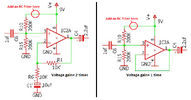
Modified values (based on articles online) marked in red.
Tried both Inverting and on-inverting circuit, Inverting op-amp circuit has more distortion , hum noise when connected, this does not happen with Non-Inverted op-amp circuit.
Input 1 and 2 is from another op-amp from microhphone UHF receiver circuit.
Modification removed microphonic effect.
Issue faced: when one of the mic (single mic) is used it works good, turned up Mic-A or Mic-B (one of the mic) volume pot to full, no distortion.
Switched on scond mic-B, turn volume up, when pot position reaching around half way howling starts, increases in volume by itself, when one of the mic volume is turned down howling stops, when both mic volume pots are at less than half no howling, but mic volume is too low.
accidentally touched pre-amp resistor on pin 2 / 6 reduced/stopped howling sound (touching causes other distortion but stops howling)
will it help if 33pf capacitor is connected in parallel across 100K resistor (feedback) ?
Requesting help to make circuit stable.
Image 1 : Refrence circuit,

Image 2: modified circuit for mixing two mic.

Modified Karaoke circuit, microphone input bass/treble input stage for removing microphonic effect on original PCB.
Issue was around Bass Treble and Echo mixer circuit. removed op-amp and related components for bass treble, replaced with circuit made on Stripboard/Veroboard
Schematic based on jrc4558 pre-amplifier circuit published in componentsinfo (Not posting URL)
posting original schematic and modified one. (water mark is there in image).
Modified values (based on articles online) marked in red.
Tried both Inverting and on-inverting circuit, Inverting op-amp circuit has more distortion , hum noise when connected, this does not happen with Non-Inverted op-amp circuit.
Input 1 and 2 is from another op-amp from microhphone UHF receiver circuit.
Modification removed microphonic effect.
Issue faced: when one of the mic (single mic) is used it works good, turned up Mic-A or Mic-B (one of the mic) volume pot to full, no distortion.
Switched on scond mic-B, turn volume up, when pot position reaching around half way howling starts, increases in volume by itself, when one of the mic volume is turned down howling stops, when both mic volume pots are at less than half no howling, but mic volume is too low.
accidentally touched pre-amp resistor on pin 2 / 6 reduced/stopped howling sound (touching causes other distortion but stops howling)
will it help if 33pf capacitor is connected in parallel across 100K resistor (feedback) ?
Requesting help to make circuit stable.
Image 1 : Refrence circuit,
Image 2: modified circuit for mixing two mic.
Last edited:
")