Continue to Site

Welcome to our site!

Electro Tech is an online community (with over 170,000 members) who enjoy talking about and building electronic circuits, projects and gadgets. To participate you need to register. Registration is free. Click here to register now.

  • Welcome to our site! Electro Tech is an online community (with over 170,000 members) who enjoy talking about and building electronic circuits, projects and gadgets. To participate you need to register. Registration is free. Click here to register now.

Multiple State LED Flasher

Status
Not open for further replies.
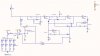
Thanks to all for the help. Dougy your circuit works great. I still need a bit of tweaking of the RC to get the timing right.

I notice the circuit must remain off for at least 4 time constants or the timing is inaccurate because of the discharge rate. Is there a way I can discharge the caps instantly or at least within a couple of seconds when the switch is turned off?
 
4 time constants? Of what? 4 flashes you mean?


Anyway, the caps are discharged through D1/R3 & D2 when the switch is open. So decrease the value of R3.

You may also wish to increase R1 & R2, so that you may decrease C2 & C1; this will also make the discharge time faster when the switch is opened.

e.g. R3 ~ 10k, R1 ~ 8.2M, R2 ~ 8.2M, C1 ~ 10u, C2 ~ 10u.
 
OK, sure. That discharge time problem was due to a bit of an oversight on my part. The discharge time constant was around 8.2 seconds. If you decrease R3 to 10k, it decreases to 1 second. If you decrease C1 & C2 to 10uf, it decreases to 100ms.

All the best.
 
Help with Flasher

Dougy83 and All,
Hopefully you are still monitoring this thread. The circuit you designed is working great but I have a few questions I hope you can clarify.

With the values I have for the timing I am getting about a 2-3 second delay in the led flash when the oscillators change states. Any idea how I might eliminate this. It is not a smooth transition from one state to the other. I have attached the schematic of what I have so far.

Also I need to replace the original one led (led18) with 8 led's that are powered by a 12V battery (feature creep). This is what I have been trying but to no avail. When I set the comparator to the led on voltage (2.7V) I get the 8 led's turning on with LED18 and flashing in the correct sequence but they will not turn off when the switch is opened. LED18 does turn off but the array remains on? If I adjust the comparator to the other side of the reference the led's will not flash but they will turn off when the switch is opened. My plan is to remove the single led (LED18) once I get the circuit working. I have a feeling you will have a simple solution, any help will be greatly appreciated as I have struggled with this one all day. Thanks in advance.

-Kelly
 

Attachments

  • Image-0124.jpg
    Image-0124.jpg
    44.7 KB · Views: 167
Any chance you can post a readable schematic. Try saving as a larger monochrome .gif file.

Also, could you attach a quick sketch of the LED waveform you're getting, and also one of what you want to achieve. Sorry, I find images easier to interpret than words.
 
Flasher Circuit

Dougy83,
I tried the mono gif and lost all resolution. Can you read this?

I will get the sketch of the desired and actual but I think my first concern is getting the 8 led array to flash and turn off in the same manner as the single led.

I will post the full led wave for of the original circuit in a few. I hope you can read these. If not I will try something else. Thanks.

-Kelly
 

Attachments

  • Image-0131.jpg
    Image-0131.jpg
    181.8 KB · Views: 167
  • tek00000-01.GIF
    tek00000-01.GIF
    37.6 KB · Views: 153
  • tek00001-01.GIF
    tek00001-01.GIF
    36.6 KB · Views: 147
  • tek00002-01.GIF
    tek00002-01.GIF
    38.7 KB · Views: 151
Last edited:
I will get the sketch of the desired and actual but I think my first concern is getting the 8 led array to flash and turn off in the same manner as the single led.

Replace U1F with a N-channel MOSFET (must turn on at VGS=VCC-0.7V): gate to R15, source to ground, drain to the LED bank (supplied from same point as LED18). I don't know what VBATT is, but you should be able to use it to supply the rest of the circuit if you use a 74C14 or 40106 IC (they can run on up to 16V supply); that'll save you from having to maintain the additional 5V supply.

Thanks for posting the schematic. I don't believe the values of the components are correct, based on the other waveforms you posted. Did you try reducing the caps from 100uf to 10uf?
 
Last edited:
I don't know what VBATT is, but you should be able to use it to supply the rest of the circuit if you use a 74C14 or 40106 IC (they can run on up to 16V supply); that'll save you from having to maintain the additional 5V supply.

Vbatt is a 12v battery voltage that will drop from 12v to about 7.4v over the operating time of the device. If I use Vbatt to power the timing circuit will this not affect the timing as the voltage drops?
 
Yes it will affect the timing slightly. Whether this is an issue depends on your requirements.
 
Status
Not open for further replies.

Latest threads

Back
Top