Continue to Site

Welcome to our site!

Electro Tech is an online community (with over 170,000 members) who enjoy talking about and building electronic circuits, projects and gadgets. To participate you need to register. Registration is free. Click here to register now.

  • Welcome to our site! Electro Tech is an online community (with over 170,000 members) who enjoy talking about and building electronic circuits, projects and gadgets. To participate you need to register. Registration is free. Click here to register now.

Multimeter's ammeter accuracy

Status
Not open for further replies.
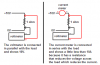
Way back in post #2 I provided the OP a little cartoon. I clearly show the load voltage measured across the load. I subsequently mentioned the voltage measured at the source and across the load will not be the same. This is because of the burden voltage drop of the ammeter. The object of this exercise in futility ( :) ) is to get the OP to understand what is going on.

Since the OP is using DMMs I did this little science experiment using some DMMs. I used a pair of identical Fluke 87 DMMs. The power source was a Lambda Model LP-532-FM 0 to 40 volt and 0 to 3 amp supply. Now as to the 100 Ohm resistor I took that seriously and coincidentally inline with what KISS mentions:

Ever seen a 4-terminal resistor? They exist.

Yeah, I saw one on my computer table a few min ago. :) I used a precision L&N laboratory grade (oil bath) good as gold fancy resistor with... four terminals.

So here is what we have.

Source Voltage = 1.500 volts.
Load Voltage = 1.475 Volts
Current = 14.75 mA.

The numbers make sense to me.

I increased the power supply voltage output until I had 1.500 volts dropped across the precision 100 Ohm load (of course measuring the load voltage at the 4 wire voltage terminals). This is what I got:

Source Voltage = 1.525 volts (an increase of 25 mV)
Load Voltage = 1.500 Volts
Load Current = 15.00 mA.

Again, the numbers make sense to me.

Now considering a kitchen table setup on a Sunday afternoon while enjoying beer I see the results as making sense to me. :)

<EDIT> Alas........

the problem got corrected by measuring the voltage across the resistor... exactly as
it mentioned above and not at the power supply, now the results from most multimeters
match the result from my calculations.

it was so simple...

This is fun stuff huh? </EDIT>


Ron
 
Last edited:
the problem got corrected by measuring the voltage across the resistor... exactly as
it mentioned above and not at the power supply, now the results from most multimeters
match the result from my calculations.

it was so simple...

That was why I was VERY specific in post #9 :D

If ohms law isn't working, then you're doing something wrong.
 
ok, that was an interesting lesson.. i almost had myself persuaded
that there is something really wrong with all these multimeters and i couldn't
undestand how come so many people can use these instruments having
a 18% tolerance.

i just couldn't think that i was reading the voltage value at the wrong
spot of that really simple test circuit.

now it's interesting to see what KeepItSimpleStupid proposed.. but first
i have to get 10M resistor could you please explain farther what happens
in that case? :D
 
This is what KISS stated:

Now try it with a 10 Meg resistor. All bets are now off.

When we measured the current through a 100 ohm resistor with 1.5 volts applied at the load we got our 15 mA. So how did the DMM measure the current? The DMM used a shunt resistor and actually measured the voltage drop across that resistor.

Give this link a read.

When we begin to get really tiny currents as in nano or pico amps things don't quite work as well. :)

This is where some precision amplification becomes our new best friend. The link compares and explains things (with cute pictures) better than I can.

Ron
 
Many regulated power supply projects have a current sensing resistor inside the negative feedback loop of its voltage regulator. Then the voltage drop of the sensing resistor is cancelled.
 
A current sensing meter is used with high voltages like 120VAC and 240AC. Then the small voltage drop across the current-sensing resistor is ignored.

But you are trying to measure the current in a low voltage circuit where the voltage drop across the current-sensing resistor in the amp-meter is a major percentage.
 
OK, voltmeters have an input Z in Ohms/Volt or just a number like 10 M ohms which is standard. Laboratory meters will have different input Z's depending on the range, but still a known constant. Electrometers are special voltmeters that have in put Z's on the order of 100 G ohms or so.

First you have to be able to measure the current flowing through a 10 M resistor, at 1 V that would be 10 uA, so you have to satisfy that first.

But if you had a 10 Meg resistor and you put a voltmeter having a 10 Meg Input Z, you suddenly have a 5 M resistor, that your measuring across rather than a 10 meg ohm one that you thought you were measuring.

if you had an old analog meter that said 20K ohms/volt and you measured a volt, you now have 10 meg in parallel with 20K.

This time, your voltmeter is perturbing the measurement, so you get a better voltmeter or use a feedback ammeter.
 
Many regulated power supply projects have a current sensing resistor inside the negative feedback loop of its voltage regulator. Then the voltage drop of the sensing resistor is cancelled.
Every power supply we ever shipped had a precision current shunt (resistor) in the negative output return. We measured load current very accurately with those. The only thing is, negative output was NOT the same as internal circuit ground of the power supply. The upside is the shunt imposed no burden at all on measuring load current and was usually more accurate than most meters.
 
Last edited:
Every power supply we ever shipped had a precision current shunt (resistor) in the negative output return. We measured load current very accurately with those. The only thing is, negative output was NOT the same as internal circuit ground of the power supply. The upside is the shunt imposed no burden at all on measuring load current and was usually more accurate than most meters.

Isn't that simply because the shunt was inside the negative feedback loop?, it doesn't matter which lead it's in, as long as it's inside the loop.
 
sorry, but i can't understand that. What do u mean with i should measure the current in series? Please explain

Note the drawing in post #2 of this thread. It shows the current meter in series and the voltmeter in parallel with the load.

Ron
 
Isn't that simply because the shunt was inside the negative feedback loop?, it doesn't matter which lead it's in, as long as it's inside the loop.
There are two different and distinct negative feedback loops: one for voltage control and one for current control or current limiting. THe CV (constant voltage) loop senses the output terminals. The CC (constant current) loop senses across the current shunt. The shunt could be in either lead but putting it in the negative line simplifies the design,
 
There are two different and distinct negative feedback loops: one for voltage control and one for current control or current limiting. THe CV (constant voltage) loop senses the output terminals. The CC (constant current) loop senses across the current shunt. The shunt could be in either lead but putting it in the negative line simplifies the design,

Yes, it's a standard method in regulated PSU's, and as you say it's often more convenient (for current limiting) to have the shunt in the negative lead.
 
Here is another sketch of a voltmeter and a current meter:
 

Attachments

  • current meter.PNG
    current meter.PNG
    11.3 KB · Views: 166
I have found the same thing, with various meters. There are some RADARs that require measuring crystal current with a Simpson 260, for just this reason. My recommendation is to get an appropriately sized shunt, and calculate the current using Ohms law. You can find them on ebay and Amazon for 25 to 30 bucks. Granted, at these prices they are not calibrated, but you can send them out for that.
 
Status
Not open for further replies.

Latest threads

New Articles From Microcontroller Tips

Back
Top