Hi there ")
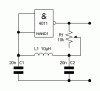
We are doing a project for school and we decided to make a automated trashbin. Very funny, but we thought of including a metal detector so if we would throw a can inside it that thing will start to make noise. But I have no clue wether I can just wind a coil around that thing (it is square shaped). The only schemes I find on the internet include 2 coils, but since it is only a trashbin I though a single coil would do well. Or am I being foolish If I would use this scheme (2 coils  ) http://www.geocities.com/tomzi.geo/metal_detector/metal.jpg I guess I would need to make some minor adjustments? Could someone help us out
We are doing a project for school and we decided to make a automated trashbin. Very funny, but we thought of including a metal detector so if we would throw a can inside it that thing will start to make noise. But I have no clue wether I can just wind a coil around that thing (it is square shaped). The only schemes I find on the internet include 2 coils, but since it is only a trashbin I though a single coil would do well. Or am I being foolish
If I would use this scheme (2 coils ) http://www.geocities.com/tomzi.geo/metal_detector/metal.jpg I guess I would need to make some minor adjustments? Could someone help us out  †
†") And I'm a beginning pic person
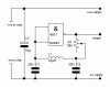
And I'm a beginning pic person  But the clue is you give that coil a frequency and it should change if metal comes trough it? But I have no clue how to do that with a pic