Continue to Site

Welcome to our site!

Electro Tech is an online community (with over 170,000 members) who enjoy talking about and building electronic circuits, projects and gadgets. To participate you need to register. Registration is free. Click here to register now.

  • Welcome to our site! Electro Tech is an online community (with over 170,000 members) who enjoy talking about and building electronic circuits, projects and gadgets. To participate you need to register. Registration is free. Click here to register now.

Thermal Power Detector TD15A

Status
Not open for further replies.

drkidd22

Member
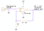
I have a thermal power detector from Thorlabs TD15A and planning on using it to measure power output from a laser. The laser has a power output range from 5mW to 20W. I was wondering if anyone here has experience with such a circuit design. I'm planning on creating a simple op-amp amplifier with a gain of about 100 and feed the analog signal into a micro-controller. If anyone has sample circuit that I can build upon or other reference material it will be appreciated.
 

Attachments

  • TD15A-SpecSheet.pdf
    731.4 KB · Views: 251
What are you trying to achieve? How does a 15mm diameter aluminium plate manage to absorb 20W without melting?

Mike.
 
Correct, it will be mounted on a heatsink. I'm more interested in designing the circuit. Was thinking of an instrumentation amplifier, regular op amp, or differential op amp.
 
One possibility, may resources onchip still left to be used. One chip.
Core is ARM M3 onchip.

Basically a DelSig, up to 20 bits, differential input, should eliminate need
for external amps. And input stage has programmable amp input. Vref
+/- .1% onchip also.

1648814709086.png

\
Other stuff onchip :

1648814827989.png


Right hand window shows resources used/left. IDE screenshot above.

Board ~ $15. Includes debug. IDE (PSOC Creator) and Compiler free.


Regards, Dana.
 
Last edited:
The sensor is rated at one millivolt per watt.
Milliwatt power levels translate to microvolt signal levels.

You need to use a high precision, self-zeroing / zero offset opamp, not any kind of generic amp, otherwise the amp errors will swamp the wanted signal.

Examples of possible parts:

That one is available from Mouser at a reasonable price:


One possibility, may resources onchip still left to be used. One chip.
Core is ARM M3 onchip.

Basically a DelSig, up to 20 bits, differential input, should eliminate need
for external amps. And input stage has programmable amp input. Vref
+/- .1% onchip also.

View attachment 136437
\
Other stuff onchip :

View attachment 136438

Right hand window shows resources used/left. IDE screenshot above.

Board ~ $15. Includes debug. IDE (PSOC Creator) and Compiler free.


Regards, Dana.

Hi this definitely looks interesting, do you have a link directly to the board?
 

Ignore the stock numbers, I think there are some around. Even check ebay.

If you wind up having a problem contact local Cypress/Infineon Area sales
manager, or FAE, or Rep.

There is also a more complete board (much more I/O) -


And this -


But the 059 board is really quite useful for many designs, and low cost.

Semi industry in a mess these days with leadtimes.

There are some boards on ebay, the 050 and 059. Caution the 050 board had a
rev on cpu, still usable w/o rev, but better off if you get correct board. CPU on
the board should not have ES1 or ES2 in its part number designation.

I believe all the 059 boards have the correct part on them.

Lastly remember on 059 you actually get two 5LP parts, one used for interface and debug,
the other the target. When done with project you snap off programmer 059 and can use
that, although its I/O severely limited. And no debug. Using it with a bootloader. You can,
at any time, reload the firmware into it to function as a programmer/debug if needed.


Regards, Dana
 
Last edited:
Came up with this circuit for now, will see how it goes.
 

Attachments

  • Thermopile Amplifier.png
    Thermopile Amplifier.png
    6.8 KB · Views: 190
Keep in mind that OpAmp does not have R-R inputs, so you are limited to -

1648844293771.png


That being said if its conversion G is 1 mV / W then you are way away from common mode input limit.
Note your circuit is sinlge ended, so if any CM noise or DC V drop occurs between sensor and input
to OpAmp you will be amping that up as well.

You have a G of 150 x 1 mV / W x 50W = 7.5 V so your positive supply must be just a little higher than
7.5V -

1648844773762.png


Regards, Dana.
 
Last edited:
I will not reach 50W. The design will be for Max of 20W, with that said the input range will be 100uV to 20mV I'm at the low end but within the -100mV Vcm at the low end.
 
Last edited:
Status
Not open for further replies.

Latest threads

New Articles From Microcontroller Tips

Back
Top