Continue to Site

Welcome to our site!

Electro Tech is an online community (with over 170,000 members) who enjoy talking about and building electronic circuits, projects and gadgets. To participate you need to register. Registration is free. Click here to register now.

  • Welcome to our site! Electro Tech is an online community (with over 170,000 members) who enjoy talking about and building electronic circuits, projects and gadgets. To participate you need to register. Registration is free. Click here to register now.

underwater fish detector

fedimakni

New Member
I would like to create an underwater fish detector - completely operating underwater (personal project)
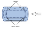
The enclosure will be a waterproof hollow cylinder (possible material to use are: acrylic, Polycarbonate or PVC), a PCB will be sealed inside that enclosure containing the sensor (the sensor of choice should not be waterproof because it will be inside a waterproof enclosure).
The fish can pass through that hollow and will be detected while passing. the inner diameter of the enclosure will be in the centimeter range to allow one fish to pass at a time.
Note:
I am not dealing with precise measurements or long range (no need for those expensive high precision sensor)
I cannot use big or expensive sensors due to budget related reasons and size constrain
max operating voltage of the PCB is 12V (preferably 5V or 3.3V)
Here's a link to picture that illustrate the idea for better understanding
I am using 2 sensors so i can make sure i detect that it passes through
optional receivers can be implemented if the sensor i use is just a transmitter and not transducer

Here comes the challenging part, the sensor choice, i will list some i thought about and i hope i can get some ideas from you that can help me.
- Ultrasonic sensor (i saw some people successfully did it but nothing is documented with low cost sensors):
Challenges:
Blind distance of ultrasonic sensor for small measurements.
I don't know if the acoustic wave can pass through acrylic hit the fish and be detected
- Optical sensor (such as VL53L1 or any other choice)
Challenges:
Require clear water
water can scatter the light but i am using it for short distance so i don't know if it will work or not
require transparent enclosure
- ESP32 camera (image recognition algorithm)
Challenges:
Require complex algorithm
Require clear water

I would like to hear if you have any other idea or if i can improve one of the suggested ideas to successfully achieve the project.
Thank you very much.
 

Attachments

  • Untitled.png
    Untitled.png
    182.9 KB · Views: 181
Get a narrow beam nearIR emitter and a phototransistor as a detector. The PhotoTransistors are available that respond to a 38kHz pulsed nearIR light source - this response to a 38kHz modulated ( pulsing) light source prevents false triggering from sunlight or other sources of IR.

The output pin on the phototransistor should go logic high when light is detected. So, you'll be looking for low signals when a fish passes to block the light beam.
 

ZipZapOuch

thanks. Could you suggest a transmitter? most of what i can find are omnidirectional emitter so not a lot of energy will be focused to the direction of phototransistor.
Any phototransistor / IR detector should work, make sure it's the type that needs the 38kHz modulated signal, they are much easier to work with and have good signal to noise discrimination.

The IR emitter (LED), can be nearly any since you have such a short range. Make sure the peak wavelength of emitter and detector are the same - typically 840nm or 940nm but others are available.
 
Just to clarify a little, if you go the 38KHz (or similar) route you DON'T use a photo-transistor, you use a special IR receiver IC, and you also need to provide a pulsed 38KHz signal for the transmitter - a continuous 38KHz signal probably won't work, as the IC's are designed to detect that as interference. You then need a missing pulse detector, to detect the beam been blocked.

It's all very easy to do with a microcontroller though.
 

Nigel Goodwin

Thanks, Yes i am going to use a uC (ESP32) why do i need to use PWM control (38khz) for the emitter? why can't continuously send the beam? does it cause a problem to do that?

If you're using a IR receiver IC then it's only sensitive to 38KHz, and also not continuously - so no 38KHz, and no pulses, and it won't work.

If you just use a photo-transistor or photo-diode, you probably need to use amplifiers to make them usable, and you really still need to modulate the IR to make it reliable. Otherwise it's susceptible to random IR causing errors.
 

Nigel Goodwin

Thanks, Yes i am going to use a uC (ESP32) why do i need to use PWM control (38khz) for the emitter? why can't continuously send the beam? does it cause a problem to do that?
You can use the ESP32. Use a simple phototransistor and simply keep checking if the sensor reads zero when the IR LED is off and that it reads higher when the LED is on. You can keep cycling until you see that the on-state is a bit less intense when a fish is in the way. IR light reflects and possibly penetrates a small fish just like light can go through your hand so it won't be zero when a fish swims through.

Your IR light may saturate the phototransistor even when the fish is there so you may have to limit the current to the IR LED to a 1 or 2 milliamps.
 
Here's an old design for an IR Fish sensor (electronics only) to give you some ideas.
I like this design. 1~2% d.f. 80 Hz, 1.25 A pulses 50mW avg., Conductive mode photo diode (missing) into integrator > differentiator> chopper > integrator > comparator.

It could easily be simplified to single supply on a single Li Ion cell with CMOS OA's but this works fine with the 741 .

Yet I prefer Vishay (nee Sharp)'s 3-terminal detectors that would work well in the remote control family pushed up around 16 kHz with 1us pulses. Then using recessed apertures on both ends with multiple Emitters and detectors, for a sharp 5~10 deg beam with more zones can be made to avoid misses and catch smaller fish. Some correlation in S/W by sequencing could do smarter things like counting sizes. These are low cost and a matrix can be done at low cost.
 
Last edited:
Your project of creating an underwater fish detector is quite intriguing! Considering your constraints and challenges, here are some thoughts on the sensor options you've listed and additional ideas:

  1. Ultrasonic Sensor:
    • Blind distance can be a challenge, especially for small measurements underwater.
    • Acoustic waves may not effectively pass through acrylic and detect fish reliably.
  2. Optical Sensor (e.g., VL53L1 or similar):
    • Requires clear water for optimal performance.
    • Water scattering can affect detection accuracy, especially at short distances.
    • Transparent enclosure is needed, which aligns with your choice of materials (acrylic, Polycarbonate, or PVC).
  3. ESP32 Camera with Image Recognition:
    • Complex algorithm required for image recognition.
    • Clear water is preferable for accurate image processing.
Considering these challenges, here are some additional ideas or improvements to your existing options:

  • Infrared (IR) Proximity Sensor: Similar to your initial idea, an IR proximity sensor can be cost-effective, small in size, and suitable for short-range detection. It can work well in opaque water and doesn't require a clear view like optical sensors. You can use two IR sensors aligned to detect fish passing through the hollow cylinder.
  • Magnetic Field Sensor: A Hall effect sensor or a magnetic field sensor can detect changes in magnetic fields caused by fish passing through.Also used underwater fishing lights to detect fishes under the water surfaces. This can work in opaque water and doesn't rely on optical clarity.
  • Pressure Sensor: While not directly detecting fish, a pressure sensor inside the enclosure can detect changes in water pressure caused by fish passing through. This can be a simple and robust method, although it won't give you direct fish detection but rather a presence indication.
  • Combination Approach: You can combine sensors for redundancy and accuracy. For example, using an IR sensor along with a pressure sensor or magnetic field sensor can improve detection reliability.
Before finalizing your sensor choice, consider testing each option in a controlled underwater environment to evaluate their performance under realistic conditions. Depending on your specific requirements and budget, one of these approaches or a combination thereof may suit your project best.
 
Last edited:
Reflection detection is easy with a high-gain bandpass filter, and AGC for automatic threshold adjustment to the off state.


Blocking overhead Fluorescent light and glass reflections is important in how the emitter/detectors are aimed and recessed with an aperture. Otherwise, they are 45 deg. Some angle if facing a glass wall is desired to block the reflection will improve sensitivity.

There are many options including angling the Tx/Rx (emitter/detector diodes)
1717452461724.png

Be sure to read the other links.

If the leads are overheated by soldering for more than 3 seconds, they may leak with moisture around the epoxy seal. So don't. A quick tinning of both ends and then reflow to join is best , <<2s.

Adding silicone to the base of the leads may help for reliability underwater. You may need a one-shot if there are multiple pulses per fish or filter in the software.

Emitter angles can vary from too wide to just right.

The only other parts needed are a resistor to limit LED current and Rx discretes.

1717451959436.png
 
Last edited:

Latest threads

New Articles From Microcontroller Tips

Back
Top