Continue to Site

Welcome to our site!

Electro Tech is an online community (with over 170,000 members) who enjoy talking about and building electronic circuits, projects and gadgets. To participate you need to register. Registration is free. Click here to register now.

  • Welcome to our site! Electro Tech is an online community (with over 170,000 members) who enjoy talking about and building electronic circuits, projects and gadgets. To participate you need to register. Registration is free. Click here to register now.

LM3886 problem...

Status
Not open for further replies.

tasos_e

New Member
Well here is my problem.
I put everything on that board I did from National datasheet and then supply it. what I get? +40 volt at the output...

The supply I use is +, - 41.8Volt.
Ok there was a miss calculation somewhere there and got a 2x30Volt 150Watt toroidal for my 2x50Watt amplifier.

Ok I know it is a bit high (at the limit of the chip). When the supply is open air I measure +41.8 and -41.8 but then when I connect it to the board and measure the supply voltage at pin 1, 5, 4 it is +38 and -38

It is strange to me that I hear everyone say how good that chip "work" and all I get is +supply at the output (pin #3), having nothing connected as input signal. Thank god I measured the output before I connect it to the speaker, or I would have them in my hand :p
I also get that +40 volt at the output, even if the mute pin has no currect drown from it.
Is it realy that power supply I use? or something else?

p.s.
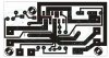
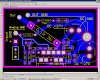
that is the circuit board I made :)
 

Attachments

  • LM3886.2.jpg
    LM3886.2.jpg
    86.9 KB · Views: 3,934
i just built an amp with the 3886 that is very similar. i doubt there is anything wrong with the chip. there could be a small piece of solder bridging between two tracks or something could be hooked up wrong. do you have a schematic for the circuit or an overlay for the pcboard artwork. i would check every connection and make sure everything is where it is supposed to be.
 
Don't you need to load the output somehow in order to test it? Even if it's just a 10k resistor?
 
:)
well I have attached the circuit board you can see it if you like.

Well
I had the boared checked and it was ok, so I made the same circuit on a testing board, the one with 2 earieas of 5 vertical rows of holes in it, and well got the same result.
Tried a new chip and again the same.
Have tried about 5 different chip with different power supply, and everytime I get the same result.

supply voltage -2Volt at the output.

Hm the chip I use are the 5 chip I got from national as a testing product...
and all do the same thing.
 
Hello Everyone.. i have a hellof an experience with LM3876 & LM3886 chips.

i have been in the JukeBox industry for many years now, almost 12 years to be exact and most of my chips were LM3876. in the past 3 years i have changed to the LM3886 because i was trying to get more wattage, and GUESS WHAT, i have found an identical problem like you have with the chip.
and i did ADD the extra +pin which is new to the LM3886 from the LM3876.

it seems that the minute you power it up, it has no Negative Voltage. the reason i know something is wrong with the chip is because they used to work without any problems. but i believe that the new chips come from china and someone screwed up the design somewhat...

the best i can offer anyone in this regard ... STICK TO LM3876 and use the 500 WAT speakers with the biggest magnet you can get on them. the amp is a GEM i can assure you all... but the new chip LM3886 has a fault in it...

i have bought in average about 50 pieces since 2007 and only 1 to 2 out of 10 worked... and my supplier refused to exchange them saying that i did something wrong... :)

the CHIPS are designed almost identical to LM3876 with a minor addition with one pin has an extra +positive pin that is all.

The LM3886 used to work also perfectly well without the extra Positive pin connected. it is not allways needed to add it enless you want that extra 10 watts of power...

tasos_e ---- STICK TO LM3876 ITS A GEM... YOUR PCB IS PERFECT IN EVERY RESPECT. CHANGE THE CHIP AND IT WILL WORK. AND USE A 500WAT SPEAKER WITH THE BIGGEST MAGNET POSSIBLE.

the chip handles extremely well the lower bass signal on its own. as speakers with low OZ in the magnet simply rattle at low frequency and this can become a nightmare for any sound engineer thinking the chips is ****. just use a big magnet with a nice 500WAT speaker and you will never GO BACK to any other sound design i can guarantee you this.

the base can sound like its a true sub woofer on its own if you split the base from the tweeter at the inputs by using a digital crossover :)

the amp itself naturally is so clear that i cannot emphasize enough on this. also remember to use a 2-OHM star ground for all Analog Grounds from the amp to separate the AC ground from Analog Ground. and NO NOISE COMES IN.

i hope i could help :) if not, email me :)

gcnegres at gmail dot com
 
I think the LM3886 is a great chip. You probably just bought chips from a bad supplier. I've had 3 of them all from a different factory and no problems. What I did notice is that one had a GBP of 2MHz, the next 4 and the next 8. They are rated with a minimum of 2MHz so that isn't a manufacturing defect, its just I wanted 8 so I had to shop around.

My point is that if you get a bad chip buy somewhere else next time.
 
Anyone that wants a Fully working proffessional LM3886 & LM3876 Design here it is.

Tip.1 the chip amp at pin 7 does not have a DC ground. it is an Analog Ground pin which goes to the DAC or input signal ground :) The chip amp simply does not need or use any DC ground at alllllllll....

Tip.2 if you use at the Input the 1UF Cap high quality, then you will not get any noises from the input wires or any interference at the inputs :)

Tip.3 Make sure you have the Grounds separated... with a 2.7 ohm resistor between DC Ground planes and Analog Grounds as shown in the design...

Tip.4 Also as i have said before... Use a GOOD speaker about 500 WAT with a nice BIG magnet... this will increase the Speaker Response time and give you the FULL benefit of the 50Wat chip which has extremely wide BANDWIDTH...

Tip.5 Do not increase the Gain resistor to more than 20K in this circuit it will give you a 20 x Gain. and DO NOT go lower than 15K. Lower Gains means MORE BANDWIDTH and higher gains means LESS bandwidth but higher output power.

Tip.6 The less the Bandwidth the more Voltage one can use. this means if you power the amp at +/-35V DC you should set the Gain at no less than 20K. if you want more sound detail then set it at 15K the gain, and use +/-28V DC and you should have a nicer sound.

Do not think that if you use a +/-28V this will decrease the sound by much if you use the right Speakers. believe me when i tell you , you wont be able to stand in front of it at +/-28V-DC if you have a good speaker of 500Wat with a huge magnet. your chest will be pounded by a hammer at 2 meters away.

PS. in the design at the output i have a 0.1 Ohm resistor which should be ignored as it is used for parallel designs. However for the best output performance with LONG speaker cables to the speakers i strongly suggest to use a 10K resistor in the output with a 0.4 coated copper wire with a 10 turn over the resistor with the ends connected to the resistor, and make sure it is ANTI CLOCK WISE from the OUTPUT of the chip...

The reason it is used is because the LONG cables become CAPACITORS due to long distances and can destroy the AMP in a split second if the capacity on the cables reverse :) so the resistor becomes a BLOCKING PROTECTION to such output SURGES... before one should consider using this resistor one must make sure that the cables are more than 10 meters from output of the amp to the speaker...

i highly recommend this amp and this design to anybody that wants to have only but the BEST.

Best to you all and i hope you will enjoy it.
 

Attachments

  • LM3876.jpg
    LM3876.jpg
    166.5 KB · Views: 3,468
I'm facing the same problem as the first post i supply the LM3886 with +-26V and at the out put i have -22V in both channels

I have build the following circuit with R3 = 1KΩ and Ci = 22u and without the potentiometer

View attachment 65916
 
Last edited:
did you run the power supply ground to the board?
 
the problem with the board in post #1 is that the input is isolated. in the data sheet example, R2 serves to ground reference the input, and provide somewhere for the input bias current (yes, this is just a big op amp) to go. with the cap at the input and no ground reference such as R2, the input bias current just charges the cap, and you get offset.
 
Last edited:
you need to ground reference pin 10. it's floating negative, and that's what's causing the offset
 
not if i'm reading the PCB layout in post #1 correctly....
 
The 22k on pin 10 should make it ground not -19 so you might look there. However if something is wired wrong it could be anything. Maybe a check of all the voltages on each pin would help.
 
yes it is, and should preferably be a star ground, which you do have, sort of... btw what's the voltage on the INPUT GROUND compared to the DC ground?
 
Last edited:
Status
Not open for further replies.

Latest threads

New Articles From Microcontroller Tips

Back
Top