Continue to Site

Welcome to our site!

Electro Tech is an online community (with over 170,000 members) who enjoy talking about and building electronic circuits, projects and gadgets. To participate you need to register. Registration is free. Click here to register now.

  • Welcome to our site! Electro Tech is an online community (with over 170,000 members) who enjoy talking about and building electronic circuits, projects and gadgets. To participate you need to register. Registration is free. Click here to register now.

LM3875 and speaker impedance questions

Status
Not open for further replies.
hmm i am confused again :)
Whiz is this the setup ur thinking ( this is what i understood). Using the drivers like this there wont be any problems with the phase (electricaly)
but for a stereo setup u need 4 woofers and 4 tw.
about the coils those transparent frames are excelent because u can count the number of turns and levels and u can see how much u must cut! i'll probably post the updated schematic for the xover tomorow.
 

Attachments

  • setup.JPG
    setup.JPG
    12.4 KB · Views: 188
Nigel Goodwin said:
a crossover in the speaker drops the damping factor considerably as well!.
Maybe at frequencies outside the pass band but who cares?

It shouldn't alter the damping factor much for frequencies in the pass band when its impedance is very low.
 
Hero999 said:
Maybe at frequencies outside the pass band but who cares?

It shouldn't alter the damping factor much for frequencies in the pass band when its impedance is very low.

It alters it in the passband as well - because you're adding an impedance in series with the speaker, and even the DC resistance of the inductor is quite appreciable. Considering it's recommended to use thick short speaker leads, to reduce the loss of damping caused by those, the inductor in the crossover will lose far more damping than the speaker leads.

But like I say, it's not a serious problem!.
 
hentai said:
hmm i am confused again

ok...check this photo! :)
**broken link removed**


hentai said:
about the coils those transparent frames are excelent because u can count the number of turns and levels and u can see how much u must cut!

yes..those transparent bobbins maybe they are excellent for the reason you said...
but my bobbins aren't exactly what you see in the photo...they are almost the same shape as the transparent, only the size is smaller and their color is black

the dimensions are:

diameter 25mm (last measurement was wrong)
center hole diameter 12mm
radius to the center hole 6mm (not to the center of the bobbin)
Height 14mm
Resistance 1,3 ohm (my multimeter has cheap cables and when i cross them i see a resistance of 0.08 ohm, i don't know if it it is important for the measurement of the coil)
 
Last edited:
The resistance of a crossover coil is about 0.1 ohms and also is the wiring from an amplifier. Total of 0.2 ohms.
The impedance of an identical speaker in series at resonance is about 30 ohms or more.
A huge difference in damping.

The resistance of the leads on my multimeter is 0.4 ohms.
 
hi whiz from ur drawing i cant see how u solved the impedance problem using only 1 woofer and 1 tw in each speaker will still lead to 4 ohm speakers. u cant put the woofer and tw in series to get 8 ohm...

the dcr of ur coils is pretty high, what diameter has the wire?
 
Last edited:
Hi!

i haven't done anything yet...it's just a thought that i could connect my woofer and my tweeter of each channel in series... :D 
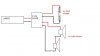
please explain why it can't be done... (we only connect 2 tw or 2 woofers?)

what's dcr? and in which cable you refer to? things are bad? nothing can be done? if that is the case...then please advice me something simple and effective so i can make things a little better.

P.S i don't have the means to move on to an upgrade of my sound system.

thank you!
 
Last edited:
Hi i will try to explain this as simple as i can..:p
u cant put the woofer in series with the tw (without a series xover) because for the signal to get to the tweeter for example it must pass through the woofer but the woofer impedance its not 4 ohm at all frequencies its only in a region lets say between 100 and 600 (mb higher mb lower depends on driver) after that its impedance is getting higher. so u can picture how much power and at what frequencies gets to the tweeter :D The tw will be hit with high power at frequencies it wont accept.
A series xover ( a first order is a capacitor in parallel with the woofer and an inductor in parallel with the tw) offers another route for the signal. So to continue with my example the high freq part of the signal wich where "blocked" by the woofers high impedance can now go through the capacitor which has a much smaller impedance at those freq. so at the tw the high freq will arive at a much higher power than the low frec. BUT! Using this type of xover sets the total impedance at 4 ohms because at high freq u will have the tw impedance (4 ohm) in parallel with the coil imp (which is much bigger) and this will result in 4 ohms imp. same at low freq the woofer impedance will be 4 ohm in parallel with the capacitor which has high Z at those freq so still 4 ohms.

dcr is the direct curent resistence
as for the problem either u make another amp or ur stuck with those 2 options that i gave u the other day
 
i have freaked out! :( :(

it's impossible to build new amp...my amp costs lot's more than the drivers! it's easier to change drivers..but this is not the right time.

If i leave my speakers the way they are..every time i raise the volume
the protection will kick in and it will lower the output! (probably! i haven't noticed it up to know...) at least my amp won't get damaged if i use it with
those drivers...right?

the crossovers i have they s*ck!! i can't put them to the speakers...the sound is very bad, no bass...highs are awful, etc.

I think i'll remove the electrolytics and i'll put two new capacitors i have two polyester 2.2μF/250V should i try them?

Hendai THANK YOU! for all your help...and i'm sorry that you did all these schematics for nothing... :( (i think i can keep them for future use...)

i'm very disappointed what can i say...
anyway! thank you all guyz...
 
What is the supply voltage of your amplifier? It can drive 4 ohm speakers if its supply voltage is not near its max. The protection circuit is activated by high voltage plus high current. If the supply voltage is lower than max then the current is also lower.

We showed you that your crossover had its parts mixed up. I think its parts values are for 8 ohm speakers.
 
audioguru said:
What is the supply voltage of your amplifier? It can drive 4 ohm speakers if its supply voltage is not near its max. The protection circuit is activated by high voltage plus high current. If the supply voltage is lower than max then the current is also lower.

We showed you that your crossover had its parts mixed up. I think its parts values are for 8 ohm speakers.

the supply is 22V it's low enough...but what good does it do that?
the diagram from the PDF shows that the output falls dramatically under 8Ω...
check the first page...
 
Im wondering couldnt he add some transistors to boost the current output? im not sure about this but i remember i've seen some amps with ic driving a complementary pair...
Whiz try and replace the capacitors and see how it sounds... there's nothing wrong with experimenting!
P.S. its hentai! :D =)))

Update: i looked again in the datasheet and i found this chart hehehe as u can see if u keep the supply under +/- 27-28V u wont have problems driving 4 ohms.
 
Last edited:
The LM3875 needs a dual supply. Yours must be positive 22V and negative 22V. If it is only positive 11V and negative 11V then there will be a very small output.

The datasheet shows it driving a 4 ohm speaker when its supply voltage is reduced from max just like I said. Its output power to a 4 ohm speaker with a dual 22V supply is 38W.
 

Attachments

  • LM3875.PNG
    LM3875.PNG
    13.9 KB · Views: 205
hentai said:
Whiz try and replace the capacitors and see how it sounds... there's nothing wrong with experimenting!
P.S. its hentai! :D =)))

ok...i will! do you think the ones i have are ok? (2.2uF/250V polyester)
sorry for the name! :D

audioguru said:
The LM3875 needs a dual supply. Yours must be positive 22V and negative 22V. If it is only positive 11V and negative 11V then there will be a very small output.

yes my supply is symetrical +22/-22! and you're absolutly right!!
it can work at 4ohm...i'm very new with electronics and i don't understand
well the specifications... :)
 
hmm.. i believe that the 2.2uF/250V polyester) are better than electrolytics and at 2,2uF they have more resistance to lower frequencies and maybe they cut wider range of low frequencies than the 3.3uF my crossover has.

I think i'll try it! :D
 
2.2uF and 3.3uF capacitors are too small for your speakers. I think the inductors are also too small. The capacitors and inductors are probably for 8 ohm speakers.

I found this crossover calculator program:
 

Attachments

  • 4 ohms, 4kHz crossover.PNG
    4 ohms, 4kHz crossover.PNG
    21.2 KB · Views: 622
Yes the capacitor seem small
for a given freq. the capacitors are higher for 4 ohm than for 8 but inductors are smaller
 
i'm bringing back this topic because my experiment was a failure...
1st order crossovers totally disappointed there isn't much difference so i am exactly where i started.

I believe the only cost effective solution is to modify my 8ohm, 2nd order crossovers
to work with my 4ohm speakers...

from an online calculator i got some values for a 2nd order crossover and i think i can easily make the modifications i only gave speaker nomimal impedance and crossover frequency and it gave me the values i need for the capacitors and the coils...so i only have to change to bigger capacitor and smaller coil, but i need help with the coils...i only know coil resistance not "mH" how can i convert mH to ohms so i can cut the coil to the proper size?

thank you!
 
Last edited:
Status
Not open for further replies.

Latest threads

New Articles From Microcontroller Tips

Back
Top