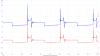
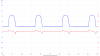
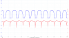
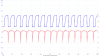
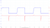
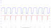
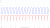
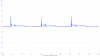
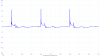
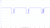
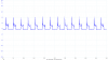
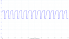
Yes I see that - but look at the attached scope traces on post #34. If you look at the red trace which is the BC547 collector output you can see that without the diodes in place, the transistor switches on much more slowly than when the diodes are in place. This has the effect of not allowing the input signal (blue trace) to pin 2 of the 555 to drop low enough, (because the edge trigger starts to raise the signal before it has been able to drop low enough to trigger the monostable). When the diodes are added, the transistor switches off sharply before the edge trigger has time to do its thing, and consequently the signal drops low enough to trigger the monostable. This is the bit I don't understand, i.e. why does adding the diodes cause the transistor to switch off more sharply? Is it because of the 1.2v lower input to the 1K resistor and its base? And, why does increasing the engine RPM gradually make it switch off more sharply, so that by the time it gets to around 2500RPM, it is triggering the monostable?
And thanks for your schematic. I will try that at some point and see how it works. I think I'll stick with the 555 for this rev counter, but I do have another that needs the same so I'll have a play with that one when I get some time.

")
")