Continue to Site

Welcome to our site!

Electro Tech is an online community (with over 170,000 members) who enjoy talking about and building electronic circuits, projects and gadgets. To participate you need to register. Registration is free. Click here to register now.

  • Welcome to our site! Electro Tech is an online community (with over 170,000 members) who enjoy talking about and building electronic circuits, projects and gadgets. To participate you need to register. Registration is free. Click here to register now.
Status
Not open for further replies.

mastro14720

New Member
Hi everyone, I am wanting to build a project that uses LEDs to "dance" or react to music. Here is a YouTube video of what I'm aiming for.


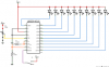
The IC I want to use for this is the LM3914. I've tested the chip using a potentiometer as a voltage divider (for the signal source) and it worked great. The schematic I used for this is attached as C1.

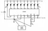
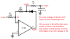
When I play music from a phone as the signal source, however, the circuit does not work properly. The circuit I used for this is attached as C2 (it can also be found in the data sheet).

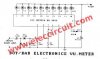
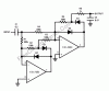
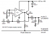
According to the data sheet for the LM3914 IC, the input signal has to be above 0 volts. To my understanding, don't audio signals dip below zero into the negative range? Could this be the reason why it is not working properly? Would I also need to use an op amp for the circuit because the output of a phone or computer isn't strong enough? After doing some digging I found a circuit that seems to solve both problems but I am not sure. This circuit is attached as C3.

The data sheet for the LM3914 can be found at this link:
https://www.ti.com/lit/ds/symlink/lm3914.pdf

Currently I am a sophomore electrical engineering student at Ole Miss, so I am no expert in this stuff. I would appreciate any help you guys could give me.
 

Attachments

  • c1.png
    c1.png
    4.6 KB · Views: 354
  • c2.png
    c2.png
    8 KB · Views: 337
  • c1.png
    c1.png
    4.6 KB · Views: 334
  • c2.png
    c2.png
    8 KB · Views: 312
  • C3.jpg
    C3.jpg
    10.2 KB · Views: 412
The only one of the schematics the rectifies the audio input signal is C3.jpg This has a voltage doubling rectifier circuit. You need a 5 volts DC signal to Light all the LEDs If we add to that about 1.4 volts to alow for the forward voltage of the two diode we need 6.4 volts. As the recifier doubles the voltage we need a peak voltage of 3.2 volts. The RMS value of a sinewave with a peak value of 3.2 volts is 3.2/1.414 = 2.26 volts RMS. So you need about 2.3 volts RMS audio signal into the voltage doubler.

Les.
 
I did some more digging and found another schematic, this time with an amp. Would the attached circuit C4 work? I have not yet learned about rectifiers, but I have been reading up on them since your reply. I think there is a half-wave rectifier in the attached schematic between the op amp and the LM3915, but once again, I don't know much about rectifiers. What is the purpose of rectifying an audio signal in regards to the project?
 

Attachments

  • C4.gif
    C4.gif
    6.9 KB · Views: 585
What is the purpose of rectifying an audio signal in regards to the project?
So that the whole of a wave cycle is used instead of just half a cycle.
 
Your schematic in post #3 should work. I would make a guess that the amplifier is an LM386 which would work with an input signal of about 25 mV. The gain control on the input would allow it to work with larger input signals. You are correct that it uses a half wave rectifier.

Les.
 
A VU meter, electronic or mechanical, will respond more quickly to some transients if the audio is full-wave rectified. This is because a step change in signal amplitude could start in the negative half-cycle, and a positive half wave rectifier would miss it. If this is not a big deal to you, then running audio centered about GND into a 3914/15 and letting the input amplifier clip off the negative voltages works (effectively half-wave rectifying the signal) fine.

ak
 
The LM3914 is a linear voltmeter that is no good for audio levels and our hearing that are logarithmic. The LM3915 is logarithmic and works well. You should use one of the "peak detector" circuits shown in the datasheet of the LM3915.

Many years ago I designed and built a Sound Level Indicator circuit that is usually powered from a 9VDC wall wart but it also has a 9V Ni-MH rechargeable battery being continuously trickle charged. Then it is also portable. The wall wart actually produces 10VDC and the battery is actually 8.4VDC.
The input is a microphone so that it shows the voices of people talking, the stereo or the TV sounds. It has a mic preamp and a half-wave precision peak detector. It uses a third transistor to provide an additional 20dB of range for loud sounds and the preamp is very sensitive for the LM3915 to show very low sound levels. Then the total range of sound levels is 50dB. An LM3914 would show a range of only 20dB and most sounds would light all the LEDs or no LEDs like an on-off switch.
 

Attachments

  • Sound Level Indicator schematic rev1.PNG
    Sound Level Indicator schematic rev1.PNG
    66.4 KB · Views: 587
  • Sound Level Indicator 002.jpg
    Sound Level Indicator 002.jpg
    47.1 KB · Views: 348
  • Sound Level Indicator 003.jpg
    Sound Level Indicator 003.jpg
    31.5 KB · Views: 310
  • Sound Level Indicator 004.jpg
    Sound Level Indicator 004.jpg
    28.4 KB · Views: 296
I have most of the IC's you will need if interested.
2 – DC-SS015 PIR motion sensors

2 - pic 16F677-I/SS

1 – LM 3916N-1 Dot bar driver 18p dip

10 – TL0741 N low noise jfet dip pkg

5 – OPA4131 QUAD FET OPAMP 14PIN SOIC

2 – PGA2311PG4 5V STERO AUD CTRL 16 DIP

4 – TLC2262AID R-R DUAL OP AMP 8-SOIC

just pm me
Ok explain where the pic and IR etc comes into this?o_O
 
It really doesn't, I am cleaning out some drawers etc. and these are included in this assortment.
OR you could use your imagination and some how incorporate into a project
 
Thanks for the quick replies everyone,
I am going to order the components and see what I can do. I should have it done after Easter break, I'll let you know how it turns out.

-Sal
 
Without a rectifier the LEDs will be a dim blur. My peak detector is a half-wave rectifier that works fine, a full-wave rectifier is not needed. The peak detector circuit lights the top LED long enough (about 30ms) for our slow vision to see it at full brightness instead of it being very dim. The circuit in post #3 has an ordinary rectifier that has a 0.7V voltage drop that messes up the very wide light sensitivity of our vision, it should be an active rectifier that uses an opamp to reduce the 0.7V voltage drop to almost nothing.
My circuit uses a transistor instead of a diode and it has another one in the feedback to the opamp to cancel the base-emitter voltage drop. The transistor can charge the capacitor much faster because it provides much more current than the opamp.
 
Ok so I tried the circuit out in post #3. After all this trouble it finally worked, but not as well as it could have as audioguro mentioned above. After researching the LM3915, I have decided to use that IC instead of the 3914 in my next build. On the datasheet I found a "precision full-wave peak detector" circuit, attached as c5 below. I plan on making this circuit and connecting the output to the 3915 , but I have a few questions. First off, what is happening in this circuit? I see the amplifiers, and I think the diodes are used for rectification, but I still don't fully understand what the circuit is doing. Why are there two amplifiers? Why are there four diodes? Is the capacitor used as a timer to set the peak-detection interval?? I know I can build the circuit, but I want to understand what is happening. My professors don't have much time with finals coming up so I thought I'd ask you guys. Once again, I really appreciate any help.
 

Attachments

  • c5.gif
    c5.gif
    18.3 KB · Views: 319
The rectifier diodes need 0.7V across them to conduct that is useless for audio that has levels as low as 0.03V. So the rectifiers are inside the negative feedback loop of opamps that reduce the 0.7V to almost zero.
The opamps have a postive supply and a negative supply.
The left opamp circuit half-wave rectifies the input positive swing and the right opamp circuit rectifies the input negative swing. D2 and D4 prevent their associated opamp from swinging almost to the supply voltage when the output swing is the polarity that is not rectified. A delay time would be caused if this happened.
The positive and negative rectified signals are mixed in the right opamp and positive voltage swings in R6 quickly charge C2 to the actual peak voltage of the audio input then a high impedance load of the LM3915 IC slowly discharges it.

My Sound Level Indicator project mentioned earlier does not have a dual polarity supply and it has a half-wave rectifier, not full wave. Its opamps work fine when their inputs are at 0V and the output can swing down to 0V.
Here is a simplified schematic of my half-wave peak detector with the Automatic Gain Control parts removed. I used a transistor instead of a diode so that it can charge the peak detecting capacitor much faster than the opamp can with a diode. The opamp cancels the 0.7V base-emitter voltage drop of the transistor so it can rectify very low signal levels.
 

Attachments

  • peak detector.PNG
    peak detector.PNG
    16.2 KB · Views: 384
I am starting to understand it, but I have a few more questions. Sorry if I am annoying, but they just don't teach you this kinda stuff in school (at least they haven't yet). How come the forward voltage for the diodes is mitigated just by being in the negative feedback loop? What is the purpose of the feedback loop? And finally, is there any advantage to having a positive and a negative supply for the op-amp?
 
Without negative feedback, at DC the voltage gain of an opamp is one hundred thousand to a few millions. Negative feedback reduces the gain to a useable amount and at the same time it reduces the forward voltage of a diode that is inside the feedback loop.
Here is a schematic showing it:
 

Attachments

  • active rectifier.png
    active rectifier.png
    17.2 KB · Views: 343
Status
Not open for further replies.

Latest threads

New Articles From Microcontroller Tips

Back
Top