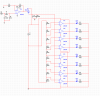
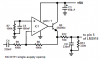
Your opamp probably will not work because it is not powered and is not biased.
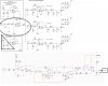
You did not read the datasheet for the LM3916 to see that its LED outputs have regulated current so the 500 ohm resistor is not needed, 500 ohms is much too high anyway. But I cannot read your writing for the resistors in series from pin 7 to ground, their total value sets the LED current.
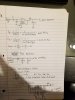
You have a huge expensive 0.68uF capacitor and a 1k resistor on the input when you could use a small less expensive 0.068uF (68nF) capacitor and a 10k resistor, or a very small 6.8nF capacitor and a 100k resistor. They cut frequencies gradually below 235Hz, no bass. Then the opamp feeds a 1k resistor that overloads it and a 0.039uf capacitor that cut frequencies gradually above 4100Hz, no highs.
The rectifier is passive and does nothing at low levels, the datasheet shows active rectifiers using an opamp so they rectify all levels.
Since you did not read the datasheet then the LM3916 might melt when many LEDs are turned on and are bright because the 12V supply voltage is much too high.
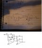
Your calculations show a passive gradual highpass and a passive gradual lowpass that together make a very poor bandpass filter. You should make an active filter in an opamp bandpass filter circuit.
Your calculations show a huge expensive 0.51uF capacitor and a 100k resistor but your schematic shows 0.051uF, which is it?