Continue to Site

Welcome to our site!

Electro Tech is an online community (with over 170,000 members) who enjoy talking about and building electronic circuits, projects and gadgets. To participate you need to register. Registration is free. Click here to register now.

  • Welcome to our site! Electro Tech is an online community (with over 170,000 members) who enjoy talking about and building electronic circuits, projects and gadgets. To participate you need to register. Registration is free. Click here to register now.

Is this information clearly enough?

Status
Not open for further replies.

Boncuk

New Member
Hello friends,

I've made a PCB design to be used in a kit.

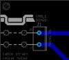
Since mains power is involved I want to make sure that sufficient strain relief is applied to the power cable by routing the cable through holes in the PCB material.

The explanation of how to do it is contained on the silk screen of the PCB.

Please take a look and tell if the drawing is clear enough to be understood well.

Thank you

Boncuk
 

Attachments

  • INFO.jpg
    INFO.jpg
    15.6 KB · Views: 268
Last edited:
Having read the post first, before looking at the image, it makes sense.

However, just looking at the silk screen without referring to any other instructions, would probably be unclear.

Since this is part of a kit, perhaps some form of large/bold warning message on the first page of the assembly instructions would be advisable. The reason? Because that's where some people building kits will skip to, regardless of any previous content.

It's only when things don't work as expected, that the entire manual is read from cover to cover. ;)

HTH.
 
It is not. Maybe draw a little silk-screen cross section of the board with solid wire curves above the board and dotted wire curves below the board to help inducate what's supposed to be going on and what dotted lines mean what, and to have the the curves be S-shaped to show the weaving above and below the board.

EDIT: I just realized you did something like that, but you used a solid-lineson your cross section whereas you used dotted and solid lines on your overhead view. They did not register in my head as the same thing. Another reason they did not register is because the lines between overhead and cross section are of different widths.
 
Last edited:
Thank you for your input dk,

The holes for the cable only allow cable diameters of max 2.5mm and I imagined drawing the cable that thick the PCB layout would look too bulky.

However I guess it looks pretty good.

Dotted lines are used in machine drawings to indicate an invisible edge or line of a part (in this case top view of the board with the cable being routed underneath partly).

Better and clearer now?
 

Attachments

  • STRAIN-RELIEF.gif
    STRAIN-RELIEF.gif
    9.6 KB · Views: 232
THe dotted part only became clear to me after I realized how the whole thing was supposed to together, which doesn't help much.
 
Looks clear to me. Two diagrams and a text explanation, not sure what else they could ask for.
 
Thanks both of you.

Dk, the top "illustration" is the side view and therefor all lines, including the cable are solid, because they are visible from that view. Of course the holes are not visible and normally should be made using dotted lines.

Anyway I guess the holes will be recognized as such. (hopefully) :)

Hans
 
Looks good to me.

I think it would be helpful if you showed the solder connection on the top diagram to make it clearer that it's the cable that will be soldered into the final connection on the right. I think it would be easier to make the connection, then.

Still, it's pretty good as is.

This thread should probably be in 'Projects' rather than ****-Chat.
 
Nothing omitted now. The solder pads are screw terminals. As you can see they have wire protection too. :)
 

Attachments

  • STRAIN-RELIEF.gif
    STRAIN-RELIEF.gif
    11.2 KB · Views: 242
This thread should probably be in 'Projects' rather than ****-Chat.

It's there already in a different way. Somebody aksed for a good and cheap way of cable strain relief. This is one.
 
Nothing omitted now. The solder pads are screw terminals. As you can see they have wire protection too. :)


This one make better picture. I new what to do with the first picture but, this one show's the termination on top.

I don't see how that could be mis-understood now.


kv
 
That is seriously fancy. Ya, there's no way that could be misunderstood.

Hate to even suggest it, but a big enough idiot will look at it and figure he doesn't need to strip the wire first...
 
WHy would you strip the wire and solder it to the strain relief holes? WOuldn't that defeat the purpose of weaving it through two holes (rather than one) in the first place?
 
Last edited:
Haha. Ya, strip the wire for the clamp, not for the holes. The wire looks like it still has insulation even in the screw terminal. I totally missed that.
 
Ah, I see. UNless you used ID terminal blocks that is.
 
Last edited:
Haha. Ya, strip the wire for the clamp, not for the holes. The wire looks like it still has insulation even in the screw terminal. I totally missed that.

:)

Nope, it's just opposite. The wires have no insulation. For what do they need it? :D

Please don't tell me to use stranded wire. -:)
 

Attachments

  • STRAIN-RELIEF.gif
    STRAIN-RELIEF.gif
    10.9 KB · Views: 242
Last edited:
Nasty wires.

Common gimme a break ? You really think someone would actually try to build it and not strip the ???????????????


OK, so maybe they would. :p


Are you accusing me.....I like my wires fully dressed I'm a bit of a prude. :eek:

Bare wires are nasty. If you don't believe me just lick your fingers and try to touch them. Ha,ha.:D


kv:rolleyes:
 
Bare wires are nasty. If you don't believe me just lick your fingers and try to touch them. Ha,ha.:D


kv:rolleyes:

Depending on the voltage you won't probably have to lick your fingers. :D
 
Status
Not open for further replies.

Latest threads

Back
Top