Electro Tech is an online community (with over 170,000 members) who enjoy talking about and building electronic circuits, projects and gadgets. To participate you need to register. Registration is free. Click here to register now.
Welcome to our site! Electro Tech is an online community (with over 170,000 members) who enjoy talking about and building electronic circuits, projects and gadgets. To participate you need to register. Registration is free. Click here to register now.
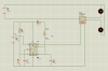
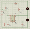
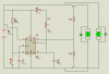
using proteus, ISIS 7 Professional I have simulate that circuit and it seems working but is it practical if i build the circuit just like in the proteus? have i put transistor, diode or other component to make the circuit more practical?
I can't find a data sheet for the relay part number you gave. The 555 has a output current spec and this needs to be met. Your relay draws some amount of current which your 555 needs to supply and you must know this number. Without a data sheet you are only guessing and this is a bad practice to get into. I suggest you obtain the relay data sheet or pick another relay where you can obtain the data sheet.
Unfortunately the current needs to flow in the wrong direction. It's OK with NMOS where the channel is ON in both directions but in bipolar devices the reverse mode beta is very low. The flyback current would end up in the esd diodes.
[edit] See correction by Dick Cappels in next message.
In the 555 (regardless of type, CMOS or bipolar) there is a transistor on the output to pull pin 3 high and there is another one to pull pin 3 low.
When pin 3 goes high, it causes current to flow into the relay coil, that current is limited by the coil's resistance and the output voltage of the 555 according to Ohm's Law.
When pin 3 goes low, the magnetic field around the relay coil will collapse, causing current to keep flowing through the coil, and to do this the coil will drive pin 3 toward ground.
If the 555 is an NE555 (with bipolar transistors), the transistor that supplied the current to the realy's coil is an NPN Darlington, the emitter of which is connected to pin 3.
When pin 3 switches low, the emitter of that NPN Darlington will continue to supply current to the realy coil as the magnetic field collapses, thus holding pin 3 near ground.
If the 555 is a CMOS version, then things are as above, except when pin 3 switches to ground, the parasitic diode that is part of the MOSFET that pulls pin 3 low will conduct the current from the relay coil as its magnetic field collapses, thus holding the voltage on pin 3 to a little below ground until the filed has collapsed.
Sorry, but I mistyped "Wiper" in my earlier reply. The wiper of the VR needs to be connected to one end of the VR or the other.
thank you for your suggestion about transistor.. can you provide me the transistor product number and what kind of transistor you use..? I want to study its function and how it works on internet.. really apreciate this..
This site uses cookies to help personalise content, tailor your experience and to keep you logged in if you register.
By continuing to use this site, you are consenting to our use of cookies.